Legende: 819393-2c
Technische Änderungen vorbehalten.
Alle Maße in mm.
V2 Variante 2
A Vorderansicht
C Draufsicht
V Detailansicht Verkleidung
W Detailansicht Wandbefestigung
Y Detailansicht Kondensatleitung außerhalb Gebäude
FA Fertigaußenfassade
UKG Unterkante Gerät
OKB Oberkante Boden
LR Luftrichtung
FS Freiraum für Servicezwecke
1 Heizwasservorlauf (Zubehör)
2 Heizwasserrücklauf (Zubehör)
5 Kondensatablauf / Syphon (Aufstellungshinweise Kondensatablauf siehe Bedienungsanleitung)
6 Konsole für Wandbefestigung (Zubehör)
8 Verkleidung Wandkonsole (Zubehör)
12 Hydraulische Verbindungsleitung
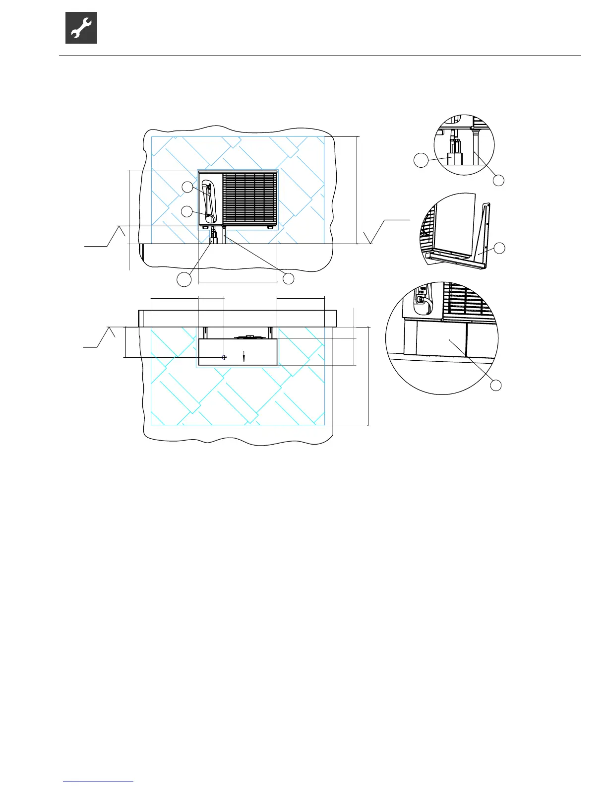
Installation plan for wall bracket
WITH HYDRAULIC CONNECTION LINE
Key: 819393-2c
Subject to technical amendments without prior notice.
All dimensions in mm.
V2 Variant 2
A Front view
C Top view
V Detailed view of cladding
W Detailed view of wall attachment
Y Detailed view of condensate line outside building
FA Complete external facade
UKG Lower edge of device
OKB Upper edge of ground
LR Direction of air
FS Clearance for servicing
1 Heating water supply (accessory)
2 Heating water return (accessory)
5 Condensate drain/waste trap (for installation notes on condensate drain, see operation manual)
6 Bracket for wall attachment (accessory)
8 Cladding of wall bracket (accessory)
12 Hydraulic connection line