2. Connectthedevicetothexedpipingoftheheat-
ingcircuitviavibrationdecoupling(stainlesssteel
corrugated pipes, accessory). You must install
them to prevent the transfer of structurally borne
soundtothexedpiping.
“Vibration decoupling installation instruction”
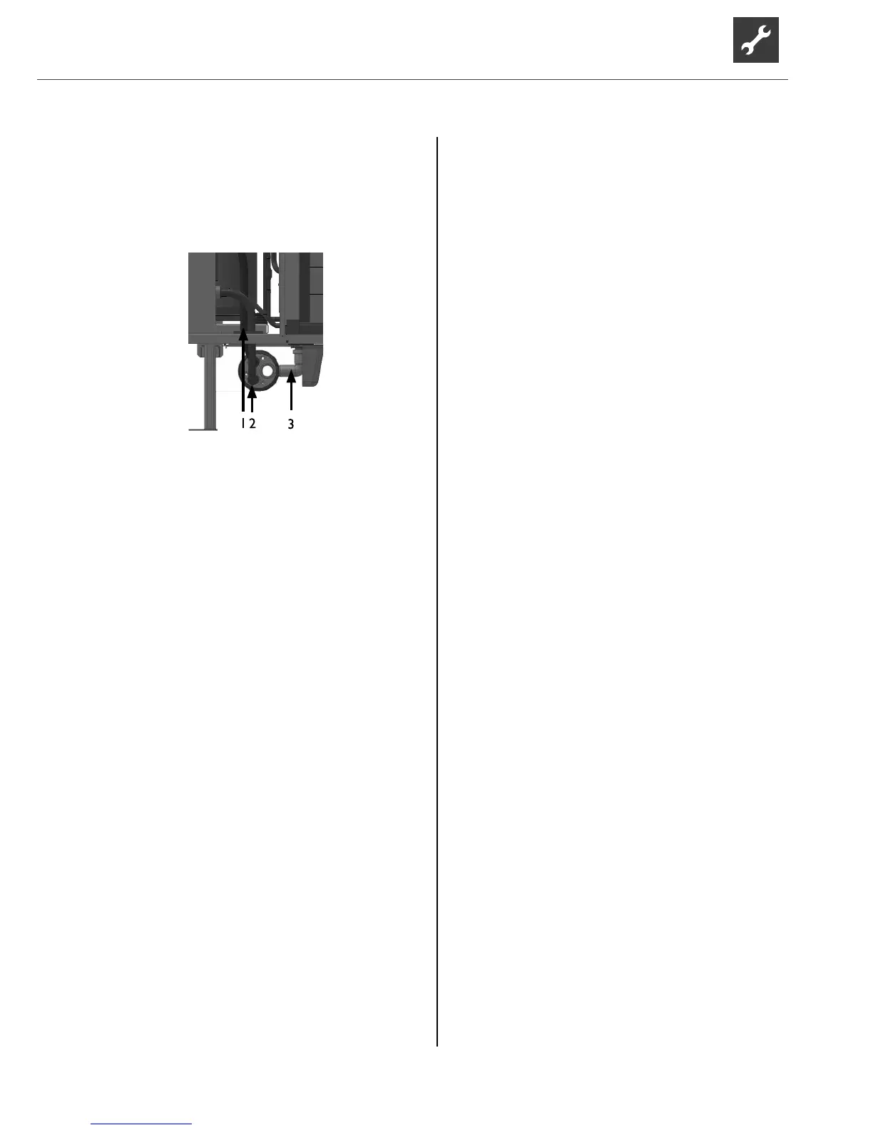
1Heatingwateroutletconnection(ow)
2Heatingwaterinletconnection(return)
3 Condensate drain pipe
3. Vibrationdecoupling(accessoryorwallductscope
of delivery):
Route the stainless steel corrugated pipes through
the feed-through in the housing oor and screw
them onto the two pipes in the wall duct.
Connectthesupplylinerst,thenthereturnline.
If no wall duct is used, route the xed piping of the
heating circuit outdoors below the frost line.
6.3 Pressure safety
Equip the heating circuit with a safety valve and dia-
phragm expansion vessel in accordance with local
standards and guidelines.
Alsoinstallllinganddrainingdevices,shut-odevic-
es and non-return valves in the heating circuit.
7 Electrical installation
Establishing the electrical connections
ATTENTION
Irreparable damage to the compressor due to wrong
rotatingeld!
► Ensureaclockwiserotatingeldforthecompres-
sor’sloadsupply(for400Vconnectiononly).
Basic information relating to the electrical
connection
● Anyspecicationsbythelocalenergysupplycom-
pany apply to electrical connections.
● Equip the power supply for the heat pump with
an all-pole miniature circuit-breaker with at least
3mmcontactspacing(IEC60947-2).
● If required, residual current circuit breaker type A
issucient.
● Note the tripping current level ( “Technical
data/scope of delivery” on page 15).
● Comply with the electromagnetic compatibility
regulations(EMCregulations).
● Install the control and sensor cables and device
supplycablesucientlyfarapart(>100mm).
● Install unshielded power supply cables and
shieldedcables(buscables)sucientlyfarapart.
● Do not extend the patch cable or bus cable. Bus ca-
bles up to a length of 30 m can be used if the quality
of the cable matches that of the original cable.
1. Route the pre-assembled 8 m cable for the heat
pump inside the building to the hydraulic unit.
2. Connect the compressor load cable to the hydrau-
lic unit using the 5-pin plug included in the heat
pump scope of delivery, “load connection to L1”.
See “Terminal diagram/circuit diagram for hy-
draulic unit”
3. Route the bus cable in a cable conduit up to the
building feed-through and from there on to the hy-
draulic unit.
4. Connect the bus cable (communication) to the
hydraulic unit using the plug included in the heat
pump scope of delivery.
5. Connect the control voltage to the hydraulic unit
using the plug included in the heat pump scope of
delivery.
See “Terminal diagram/circuit diagram for hy-
draulic unit”
Maximum line length: 30 m.