Voltage
This procedure shows to configure the Series 800/850 TEC Controllers for use with
a Voltage input in the range of 0 to 10V.
Setup the hardware for Voltage Operation:
ç Before changing the jumper settings on the Series 800/850 TEC
Controllers, remove ALL connections (including the AC power)
from the rear of the instrument and remove the cover.
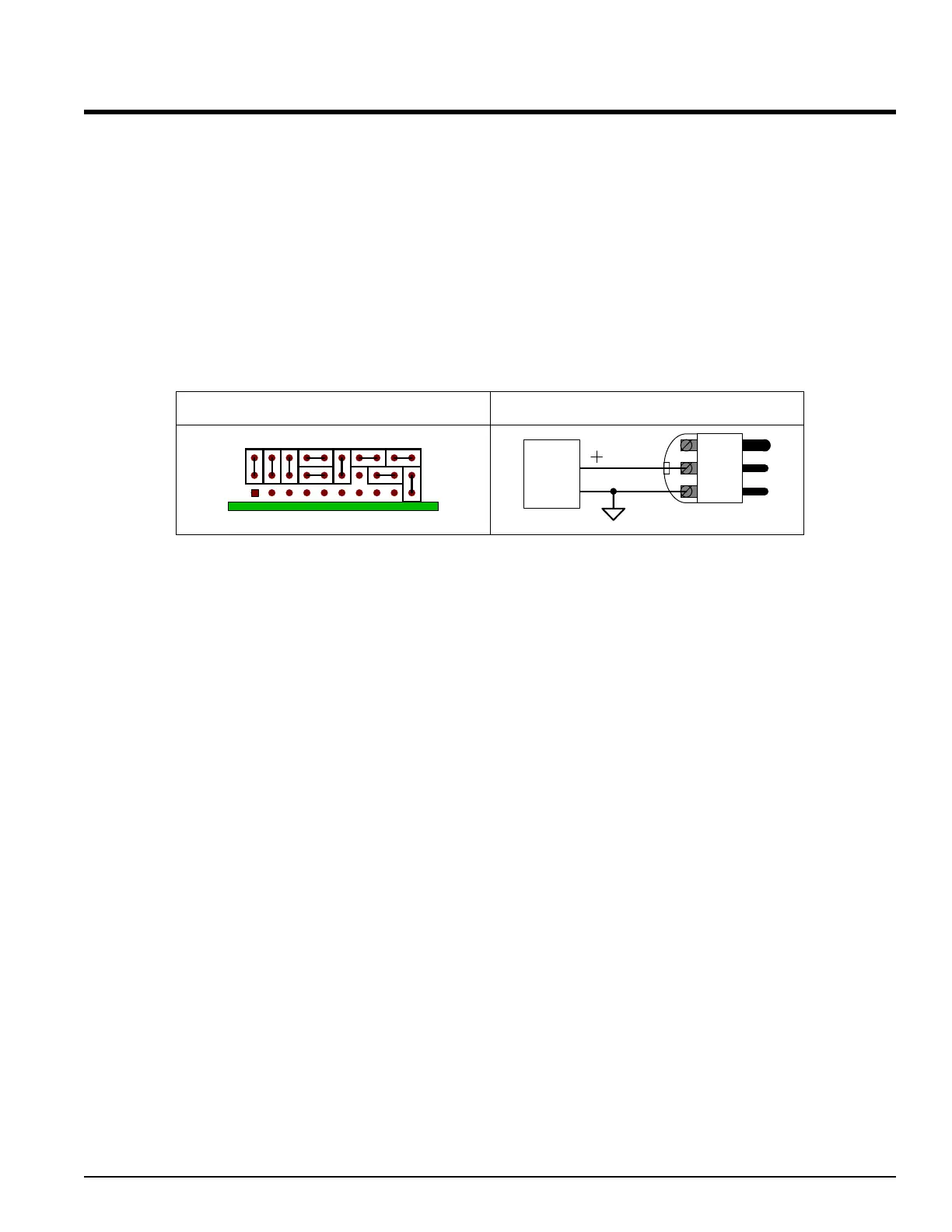
¾ Set the Jumpers as follows:
NEG
POS
GND
Voltage
Mating Connector
0 to 5V
1 to 5V
0 to 10V
VOLTAGE
PCB
Rear Panel ConnectionsJumper Settings
ç Replace the cover of the Series 800/850 TEC Controllers by
sliding it back over the top of the controller and replace the
screws that were removed. Reapply ALL connections.
Front Panel Programming
Pressing ¿¯ simultaneously for 6 seconds will get you to the [`set] Menu in the
bottom display. Cycle through using ¿ or ¯ until you reach [inp1] in the top
display, then press ‰. Cycle through using ‰ to select the parameters to change in
the bottom display. Change the parameters by using the ¿ or ¯ arrows.
1. [Sen1] = [Proc} Remember the parameter to change is in the
lower display.
2.
[In`1] = [0-10] Choose any one of the voltage ranges
available.
3. [deC1] = [)000] Change [deC1] first before [rL`1] & [Rh`1]
since changing the decimal point will
automatically load defaults into
[rL`1] &
[Rh`1].
4. [rl`1] = [)000] Range Low in Volts.
1
5. [rh`1] = [(999] Range High in Volts. (See footnote)
6.
[Ftr1] = [``!0] Filter, this is optional. See Chapter Five
under “Filter Time Constant” for more
information.
Using the ‰ button, cycle through until you reach [inp1] in the top display, then
press the ¿ or ¯ arrows until you reach [Out1] in the top display, then press ‰.
ALPHA OMEGA INSTRUMENTS CORP. Instruction Manual
Series 800/850 Thermoelectric Cooler Controller Page 36
1
The [rL`1] & [Rh`1] parameters can be scaled to engineering units if desired. For instance if 0 to 10V equals 0 to 50°C
then enter
[0)00] in [deC1], [0)00] in [rl`1], and [5)00] in [rh`1]. This will yield a setpoint of 0 to
50.00°C for a corresponding input of 0 to 10V.
 Loading...