25
GRUPPO DI
CARICAMENTO
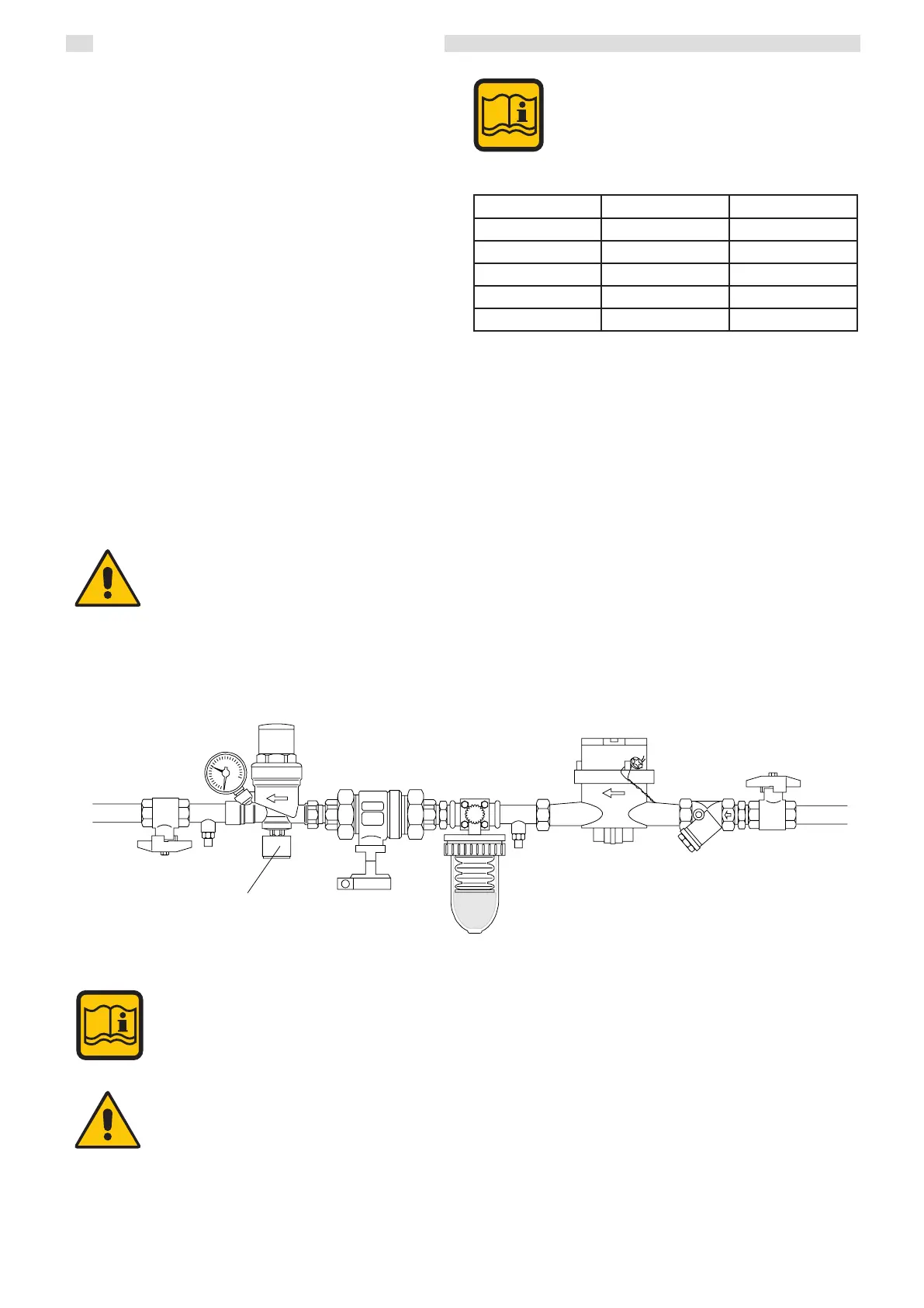
3.11 SYSTEM FILLING AND EMPTYING
Once all of the connections for the system have been
set up, it is possible to ll the circuit.
To ll the system it is possible to set up a loading valve
on the system's return pipe.
EXAMPLE OF SYSTEM LOADING UNIT
A load cock must be provided on the central heating
circuit in order to ll the system, or use the optional
accessories.
e boiler is equipped with its own draining valve, 14.
is valve must never be used to empty the system,
since all of the dirt contained in the system may ac-
cumulate in the boiler, jeopardising smooth operation.
erefore, before using the draining valve, make sure
that the system’s interception cock situated under the
pump has been closed. e system must be equipped
with its own emptying valve, of a suitable size for the
ow rate of the system.
LOADING
UNIT
Instructions for the installer
3.15 CONNECTING THE FLUE
Condensing boilers produce ue products at very low temperatures,
generally below 84°C (approx). It is therefore necessary that the ue
is impervious to the condensate produced and built with suitable
corrosion-resistant materials.
e connecting joints must be sealed and equipped with suitable gaskets
to stop condensation from leaking out and air from getting in.
In terms of ue section and height, it is necessary to refer to national
and local regulations in force.
Refer to regulations in force for sizing.
In order to avoid the formation of ice during operation, the temperature
of the inside wall at every point in the ue system, for its entire length,
must not drop below 0°C.
e ue system must comply with local and national regulations.
e ue system must be built using materials that are resistant to the
combustion products, typically 316 certied stainless steel or plastic
materials, such as PVDF (polyvinyldimethyluoride) or PPS (simple
translucent polypropylene) or aluminium or other materials with
the same features, in observance of regulation in force.
e supplier is excluded from any contractual and
extra-contractual liability for damage caused by
errors in installation and use due to failure to observe
the instructions provided by the manufacturer.
Model Modules Flue spigot diameter
440 4 250
550 5 250
660 6 300
770 7 300
900 8 300