36
3
1
2
4
Instructions for the installer
3.12 ONSITE MEASUREMENT OF THE
COMBUSTION EFFICIENCY
3.12.1 ENABLE THE CALIBRATION
FUNCTION
ATTENTION!
Function reserved exclusively to Authorised Service
Centres.
ATTENTION!
is function is explained in chapter 6 (Generator
control) of the HSCP installation and maintenance
manual.
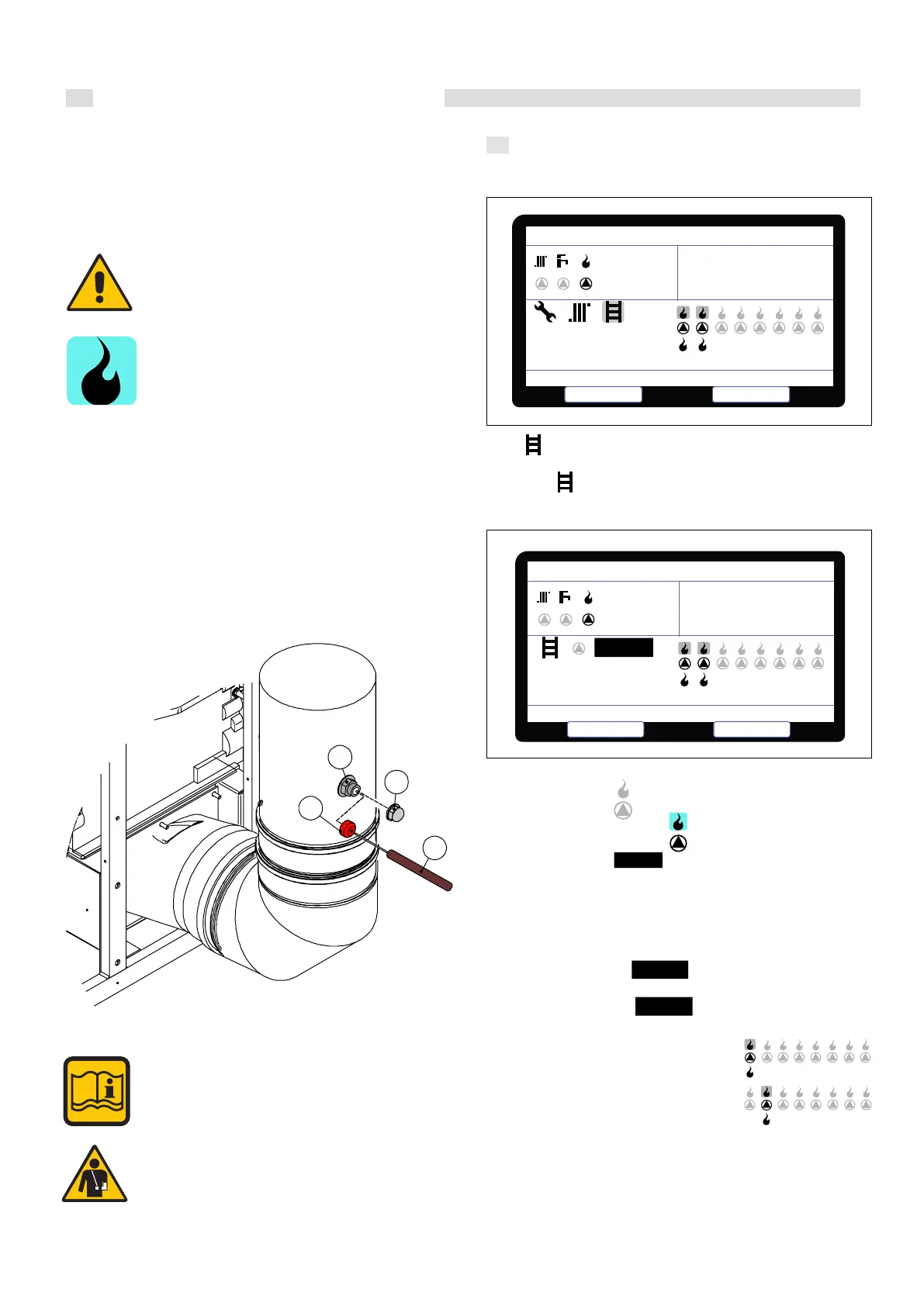
3.12.2 POSITIONING THE PROBES
In order to determine the combustion eciency, the following meas-
urements must be taken:
- measure the combustion air temperature
- measure the ue gas temperature and content of CO
2
withdrawn from
the hole 2.
Take the specic measurements with the generator at full speed (see
Par. 3.12.1).
All boilers leave the factory calibrated and approved,
nevertheless, if the calibration conditions need to be
changed it is necessary to re-calibrate the gas valve.
ATTENTION!
Remove cap 2, attach the red cap 3 to the ue point 1.
Place the CO
2
analysis probe 4 in the hole on the cap.
Once the measurement has been made, take the cap
out and use the relative cap 2 to close the ue exhaust
point back up.
Instructions for use
1.7.3 CALIBRATION FUNCTION SELECTION
Go to with knob “C” and conrm with key A (enter the access
code 0000).
Go again to
1.7.4 MAXIMUM/MINIMUM POWER
Use knob “C” to go to
Conrm with key “A” to display
0
%
Use knob “C” to go to
Conrm using key “A”
Use knob “C” to adjust the power that calibration is to be implemented
at and conrm with key “A”.
11
%
• MINIMUM POWER =
• MAXIMUM POWER =
100
%
Calibrate each heating element by selecting
the burners:
1.7.5 DEACTIVATION
Aer calibrating, press key “B” to go back to the home page.
Select
Calibrat e f unction
Generator Management
°C
100
%
85
25
°C
Escape
Modulation level
°C
100
%
85
25
°C
100
%
Select
Escape
Generator Management
100
1