50
Inspectio
ns and maintenance
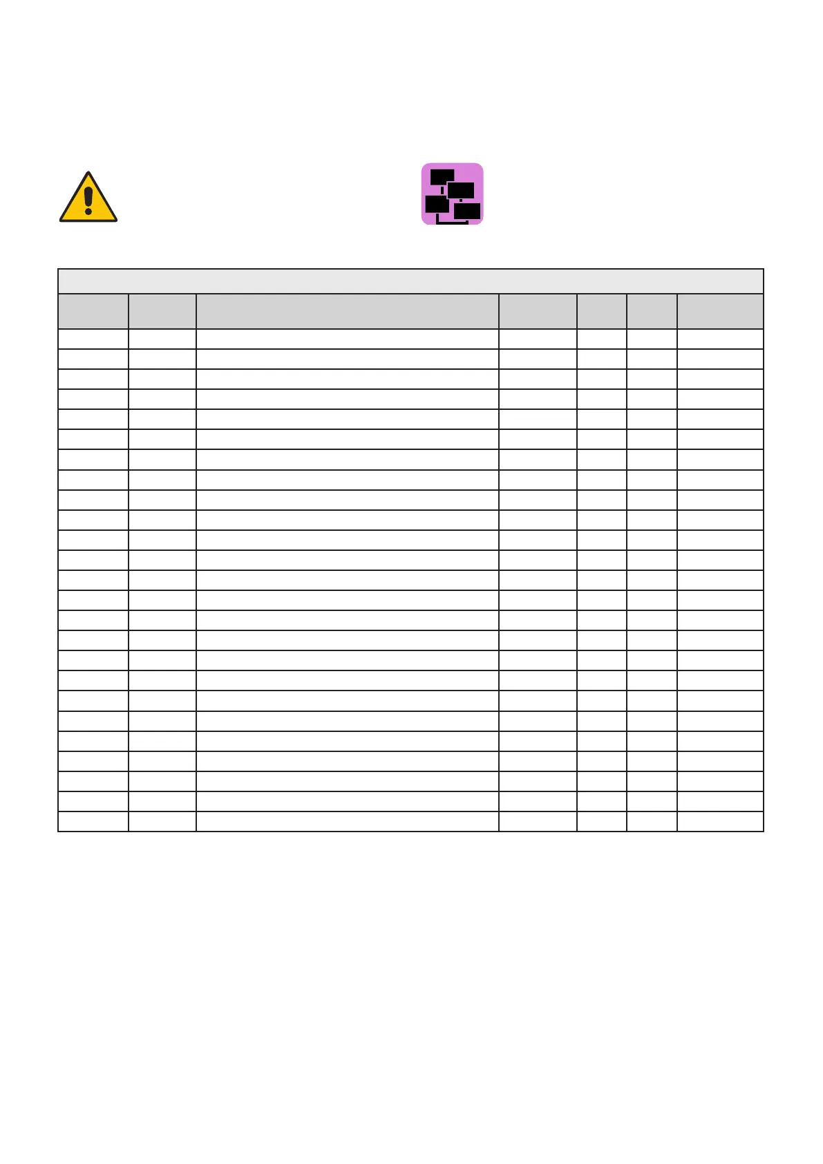
BMM parameters
Code Symb. Description Unit Min Max
Factory
settings
31 HL CH: Minimum Setpoint (°C *10) °C 20 45 30
39 HH CH-: Maximum Setpoint (°C *10) °C 50 90 95
322 Po Pump Post-circulation min. 0 10 5
309 St Application 0
619 IG Ignition Modulation % 0 100 80
314 Sb Standby Modulation % 0 100 26
319 FH Maximum Modulation % 0
100
98
346 FL Minimum Modulation % 0
100
22
488 Fb Fan 1 20 50
527 PU Fan: Pul./Rev 2 3 2
2590 bC Burner Power kW 1 1000 50
483 rP Gen: Temp. Max Dierential °C 0 50 30
622 FS Minimum Flow Sensor 0 1 1
34 HY Burner Hysteresis °C 5 20 5
336 Hs Temperature Gradient °C/min 1 30 10
353 Hp CH temperatures: Reg. Proportional % 0 50 25
354 HI CH temperatures: Reg. Integrative % 0 50 12
478 Hd CH temperatures: Reg. Derivative
% 0 50 0
486 FP Fan speed: Reg. Proportional % 0 50 4
487 FI Fan speed: Reg. Integrative % 0 50 8
337 Fr Modulation gradient rpm 0
30000
5280
526 FM Fan: Absolute max speed revs/sec 50 120 100
777 AFC Burner air ow control 0 1 0
793 COC Chimney Obstruction Sens.: Enabled / Disabled 0 1 1
768 LG Min. Gas Pressure Sens. 0 1 0
4.2 PROGRAMMING THE OPERATION
PARAMETERS
ATTENTION!
Function reserved exclusively to Authorised Service
Centres.
ATTENTION!
is function is explained in chapter 8 (Device man-
agement) of the HSCP installation and maintenance
manual.