37
All of the instructions below are provided for the
exclusive use of authorised assistance personnel.
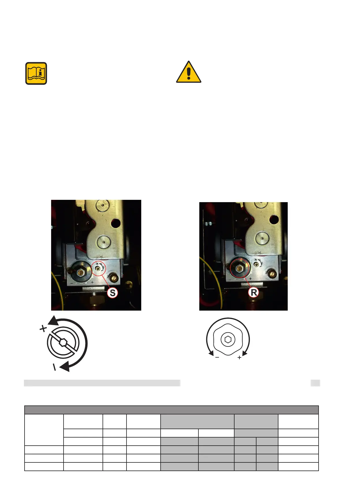
3.13 BURNER ADJUSTMENT
(S)
MAXIMUM POWER
ADJUSTING SCREW
(R)
MINIMUM POWER
ADJUSTING SCREW
- Remove the cap and insert the CO2 analysis probe into the ue gas
output of the intake/exhaust terminal, see chap. 3.12.2.
All boilers are factory calibrated and tested. If necessary,
recalibrate the gas valves (MODULE1, MODULE 2, etc.)
2) Adjustment at minimum power:
- Start the boiler in “calibration” mode at MINIMUM POWER (see
3.12.1)
- Once the burner is on, check that the CO2 value at “MINIMUM”
power corresponds with what is indicated in the “NOZZLES - PRES-
SURES” table.
- If necessary, correct the value by turning (using a 2.5 mm Allen
key) screw “R”; CLOCKWISE increases it and ANTICLOCKWISE
decreases it (refer to the “NOZZLES - PRESSURES” table).
1) Adjustment at maximum power:
- Start the boiler in “calibration” mode at MAXIMUM POWER (see
3.12.1)
- Once the burner is on, check that the CO2 value at “MAXIMUM”
power corresponds with what is indicated in the “NOZZLES - PRES-
SURES” table.
- If necessary, correct the value by turning adjusting screw “S”
CLOCKWISE to decrease it and ANTICLOCKWISE to increase it
(see the NOZZLES-FLOW RATES-PRESSURES table).
Instructions for the installer
ARES TEC ErP: 440-550-660-770-900
Type of
Gas
Supply pressure Ø Noz-
zles
Diaphragm Fan speed CO
2
levels Power at ignition
[mbar] (mm) [mm] Min
.
Max
.
[%] [%]
FL Min
.
FU Max
.
Min
.
Max
.
IG
Nat. gas (G20) 20
9
-
28 108 8.8
8.8
50
Nat. gas (G25) 25 9 -
28 113 9.1 8.5
50
Propane (G31) 37
9
-
28 101 10.8 10.6 50
NOZZLES - PRESSURES - FLOW RATES TABLE
+/- 0.2%