Appli ca ti on
3.3 BCM PARAMETERS HSC 0-10v set up
GENERAL SETTINGS /
USE SETTINGS WITH HSCP
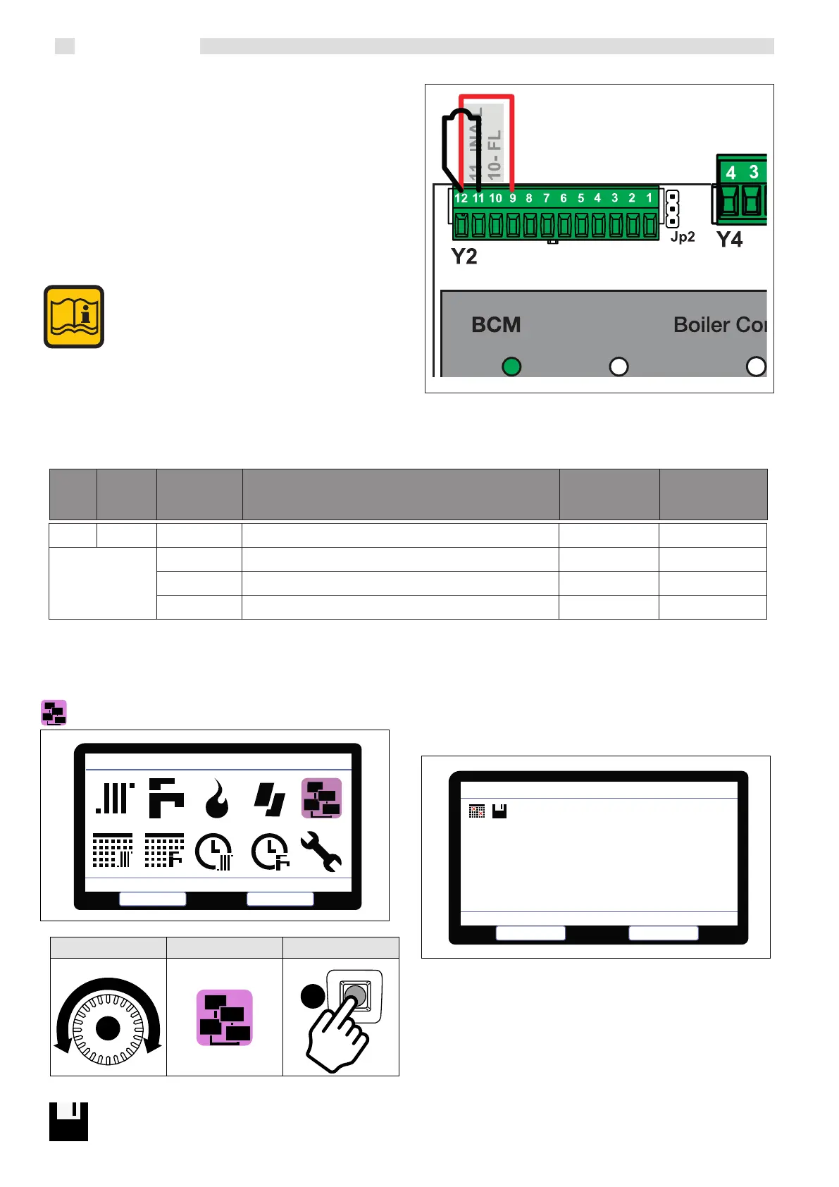
The BCM receiver is factory preset for control via 0-10V in tempera-
ture. (Control via EXTERNAL TEMPERATURE CONTROL 0-10 V).
To enable the 0-10 V request, the contact must be closed between pin 12
and pin 9 with a
jumper or with a command coming from the external
temperature control together with 0-10.
Also jumper pin 12 and 11 (ISPESL alarm input) or use it to manage
the system’s safety devices, with the contact open, all the generators are
switched o with alarm triggering.
When using the BCM coupled with HSCP, the fol-
lowing parameters must be modified
Parameter 376 change to (0)
Parameter 799 changed to (2) 0r (3)
Parameter 31 & 39 Min and Max set point
Connecting a storage
tank probe, Stemp ACC, in automatic mode, the
parameter 803 Srv assumes the value 27
and the system re-
configu-ration is
requested on HSCP (actually saving the new
configuration).
1.9 DEVICE MANAGEMENT
Devices Management
Select
Select
Escape
C
A
ROTATE POSITION SELECT
Wait for scanning device (1 minute); to save click:
1.9.1 DEVICE MANAGEMENT SELECTION + LOG
e display shows the devices in the system (- = not present/1-8 =
progressive number of the detected device
• HCM (BCM cascade controller)
• SHC (multifunction module)
• BMM (burner management board)
Select the module with knob “C” and conrm with key “A ”. e services
provided by the device, parameters and soware version are displayed.
HCM:
BMM:
SHC:
1
1
1
* * *
2
* * * * * *
Errors History
Select
Escape
Devices Management
376 DI1 Programmable Input #1
0 CH Service Enabling 0
1 Heat generator enabling 1
2 Reset alarms
Code Symb. Value Description
Factory setting
BCM use setting
with
HSCP
41