Service manual AlphaCom XL transceiver Rev. 1.4 10-08-2011 Blz. 13/74
HARDWARE INSTALLATION
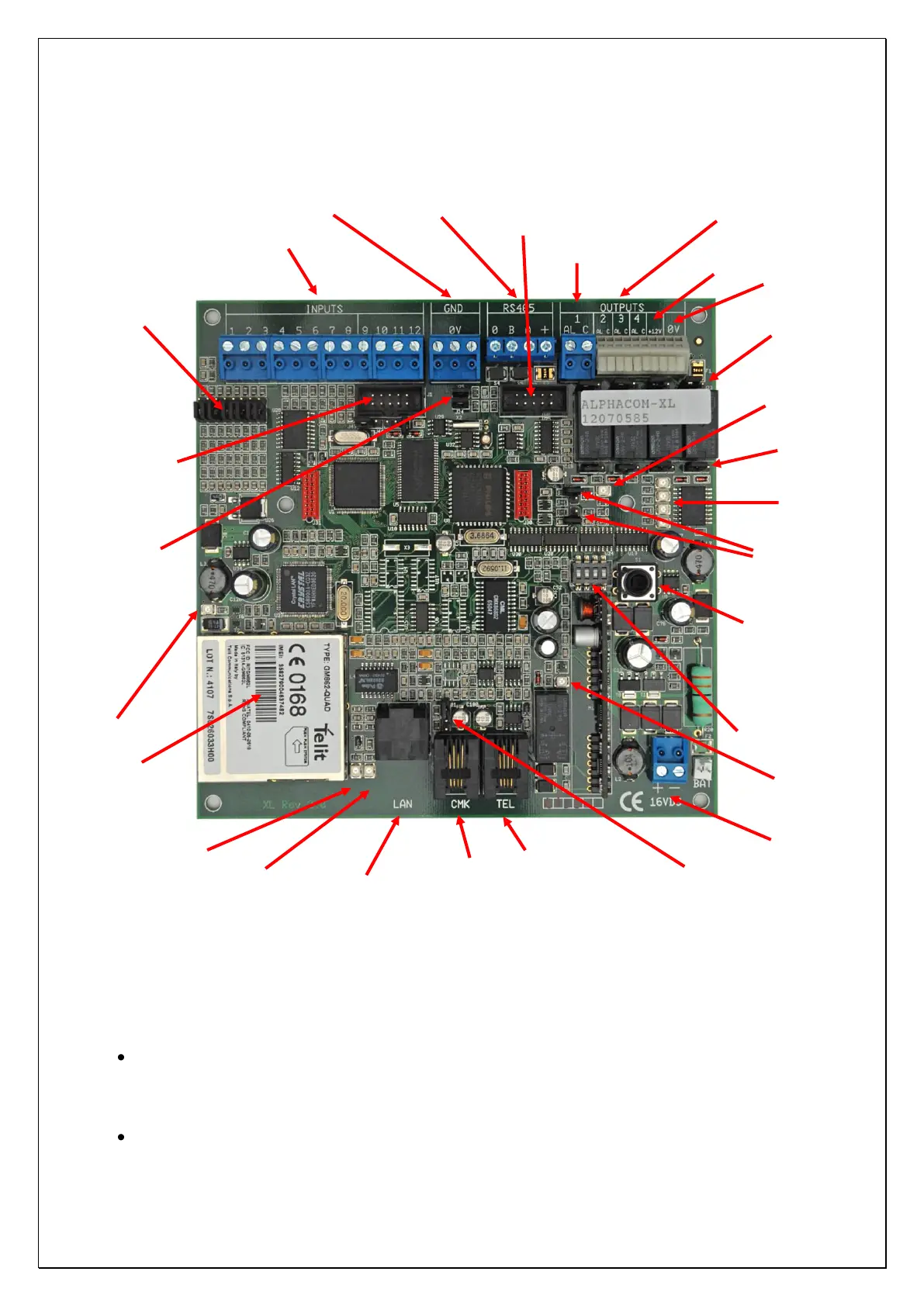
Figure 2: ALPHACOM XL connections
The AlphaCom XL transceiver is powered through the +-16VDC terminal blocks
Attention: when using the RS-485 bus you must take into consideration:
the AlphaCom XL receives is power supply through the -+16VDC connections. This is always the
case when the AlphaCom XL is delivered including power supply and batterypack in a synthetic
casing. In this case for the RS-485 bus connections only the 0V, A and B wires must be connected.
The +-terminal connection of the RS-485 bus must not be connected.
the AlphaCom XL is powered by the RS-485 bus.
Backup Telephone line
connection
LAN activity LED
(see LEDs)
Jumpers t.b.v. ingangen
(spanning sturing ja/nee)
Red LED: Priority switch
of the Alarm dialer
is active
RS-485 bus connection (serial port 2)
Jumpers for
firmware update
4x jumper to
select OC
output instead
of relay output
4x jumper to
connect C-
contact of the
relay with +12V
RS-232 for flashing firmware(serial port 1)
Jumper for PSTN
tamper loop
RS-485 master/slave:
remove when using in
combination with
AlphaVision NG