Service manual AlphaCom XL transceiver Rev. 1.4 10-08-2011 Blz. 16/74
Relay outputs
The AlphaCom XL is equipped with 4 potential-free relay outputs. Outputs 1 to 3 can be activated by the
end-user through the webinterface. Output 4 is the so-called trouble relay. This realy contact can be
programmed to activate in various trouble situations. For programming options refer to the section „output
programming‟.
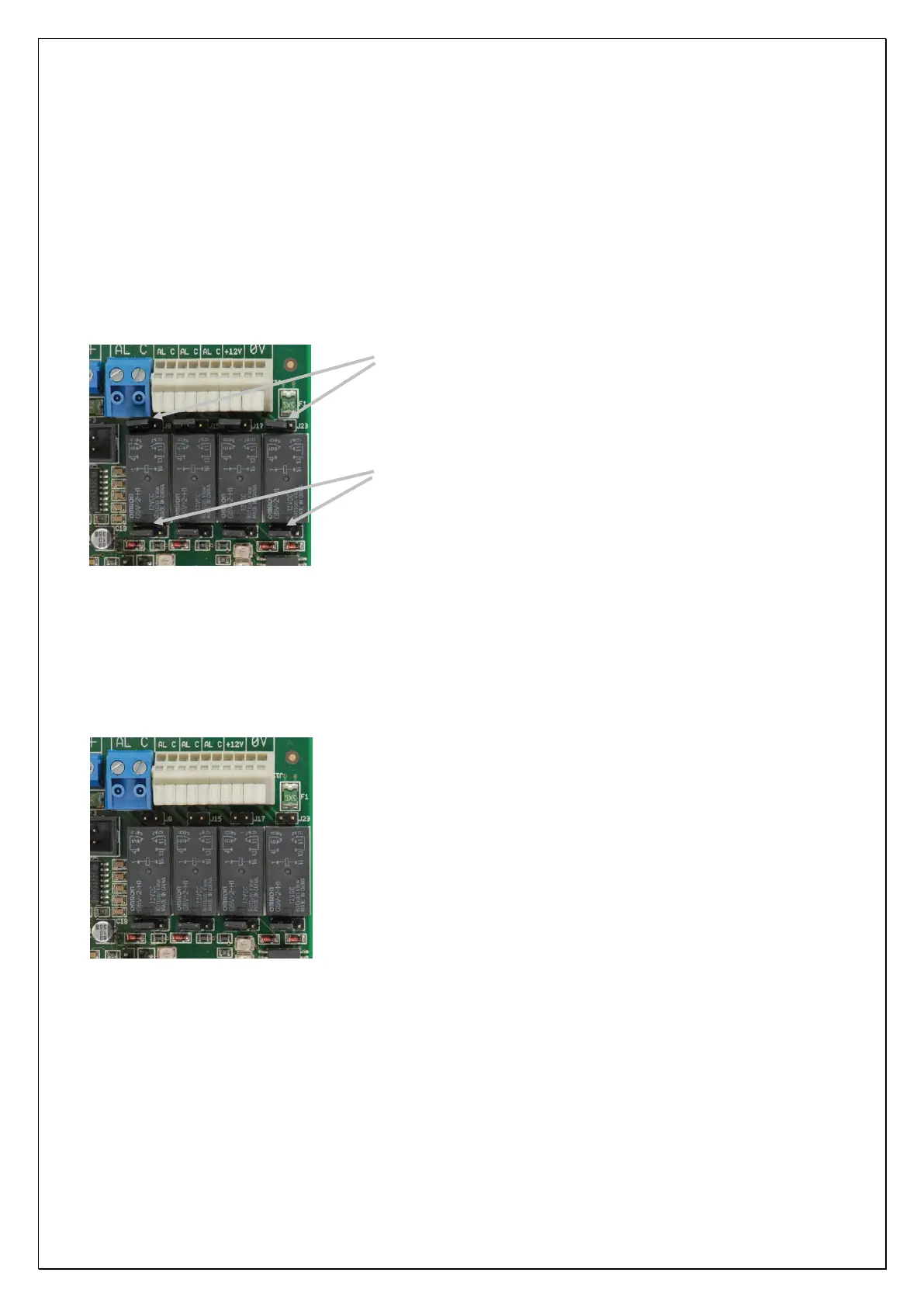
In the default situation the terminal blocks AL1/C1, AL2/C2, AL3/C3 and AL4/C4 are normally open
potential-free relay contacts. Above the relays you will find a row of 2-pin headers. These 2-pins headers J8,
J15, J17 and J23 contain a jumper but are not connected together by the jumper.
From left to right: pin headers J8, J15, J17 and J23.
From left to right: pin headers J10, J16, J22 and J27.
Figure 5: Jumper settings for relay
When the jumpers on the 2-pins headers J8, J15, J17, and J23 are placed over both pins the common contact
(C1,C2,C3 and C4) is connected to the +12V. This means that once the relay is activated (normally closed)
the common contact is connected to the alarm contact and thus applying +12V to the alarm contact. By
default the jumpers are only placed on 1 pin of the 2-pins header.
Attention: when using this option the maximum current drain of all 4 relay contacts together must not
exceed 500mA. The maximum current drain is protected by an automatic fuse (polyswitch).
If this option is not used the jumpers may also be removed as shown in
this illustration.
Under the relay contacts a row of 3-pins headers J10, J16, J22 and J27 are situated. The position of the
jumper on pin headers determines whether the outputs AL1, AL2, AL3 and AL4 are relay contacts or Open
Collector (o.c.) outputs. The jumpers settings displayed in figure 5 illustrate the default position. All outputs
are set to operate as a relay contact, the jumper is placed over the left and middle pin.