Service manual AlphaCom XL transceiver Rev. 1.4 10-08-2011 Blz. 14/74
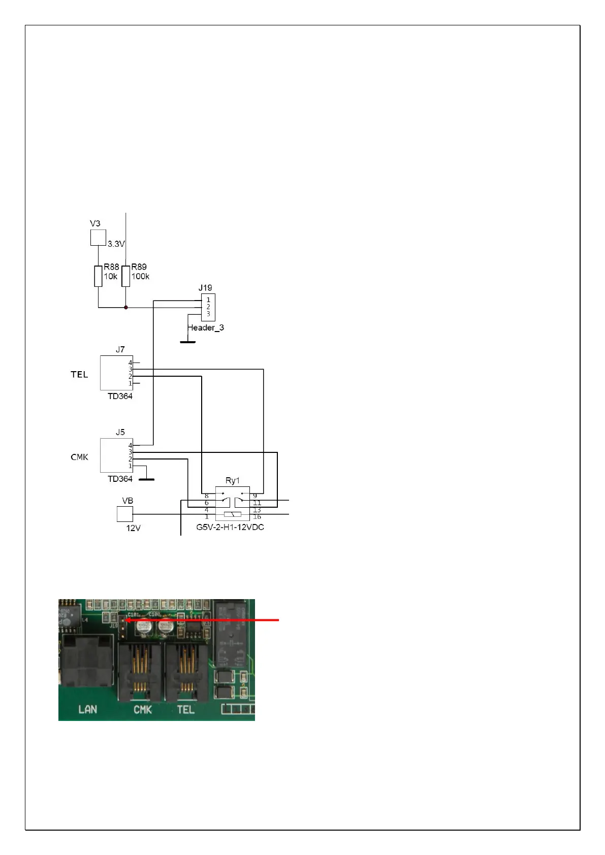
The analog dialer of the control panel is connected to the alarm dialer RJ-11 input (marked with CMK). The
two center wires (2 and 3) are used voor the analog telephone connection (A/B line), the two outer wires (1
and 4) are used as a tamper loop.
PSTN tamper loop
The AlphaCom XL is equipped with an option to monitor the cable connection between the analog dialer of
a control panel and the PSTN input on the AlphaCom XL board. To use this option jumper J19 must placed
across pins 1 and 2. The outer 2 wires (1 and 4) of the telephone cable are used. Both wires 1 and 4 should
be connected together on the side of the dialer in the control panel. To clarify the tamper loop solution see
the schematics below:
Figure 3: Schematics PSTN tamper loop
Jumper J19 is easy to find using the picture below:
Figure 4: Jumper for PSTN tamper loop
J19 is to select the PSTN tamper loop option.
Pin 3 of the schematics (0V) is the top pin of
the 3.