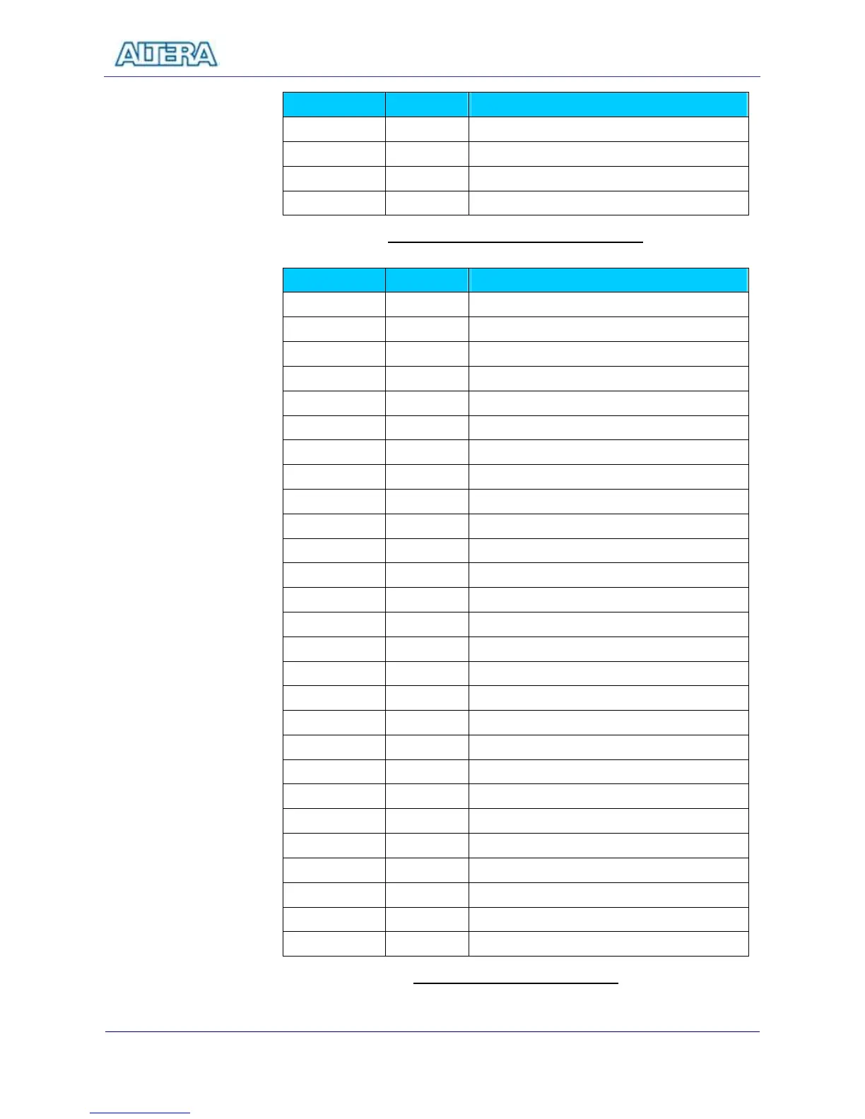
Description
KEY[0] PIN_G26 Push Button[0]
KEY[1] PIN_N23 Push Button[1]
KEY[2] PIN_P23 Push Button[2]
KEY[3] PIN_W26 Push Button[3]
Table 3.4 Pin Assignment for Push Buttoms
Signal Name FPGA Pin No.
Description
LEDR[0] PIN_AE23 LED Red[0]
LEDR[1] PIN_AF23 LED Red[1]
LEDR[2] PIN_AB21 LED Red[2]
LEDR[3] PIN_AC22 LED Red[3]
LEDR[4] PIN_AD22 LED Red[4]
LEDR[5] PIN_AD23 LED Red[5]
LEDR[6] PIN_AD21 LED Red[6]
LEDR[7] PIN_AC21 LED Red[7]
LEDR[8] PIN_AA14 LED Red[8]
LEDR[9] PIN_Y13 LED Red[9]
LEDR[10] PIN_AA13 LED Red[10]
LEDR[11] PIN_AC14 LED Red[11]
LEDR[12] PIN_AD15 LED Red[12]
LEDR[13] PIN_AE15 LED Red[13]
LEDR[14] PIN_AF13 LED Red[14]
LEDR[15] PIN_AE13 LED Red[15]
LEDR[16] PIN_AE12 LED Red[16]
LEDR[17] PIN_AD12 LED Red[17]
LEDG[0] PIN_AE22 LED Green[0]
LEDG[1] PIN_AF22 LED Green[1]
LEDG[2] PIN_W19 LED Green[2]
LEDG[3] PIN_V18 LED Green[3]
LEDG[4] PIN_U18 LED Green[4]
LEDG[5] PIN_U17 LED Green[5]
LEDG[6] PIN_AA20 LED Green[6]
LEDG[7] PIN_Y18 LED Green[7]
LEDG[8] PIN_Y12 LED Green[8]
Table 3.5 Pin Assignment for LEDs