6
18 Red User LEDs
50MHz Oscillator and 27MHz Oscillator for external clock sources
24-bit CD-Quality Audio CODEC with line-in, line-out, and microphone-in
jacks
VGA DAC (10-bit high-speed triple ADCs) with VGA out connector
TV Decoder (NTSC/PAL) and TV in connector
10/100 Ethernet Controller with socket.
USB Host/Slave Controller with USB type A and type B connectors.
RS-232 Transceiver and 9-pin connector
PS/2 mouse/keyboard connector
IrDA transceiver
Two 40-pin Expansion Headers with diode protection
DE2 Lab CD-ROM which contains many examples with source code to
exercise the boards, including: SDRAM and Flash Controller, CD-Quality
Music Player, VGA and TV Labs, SD Card reader, RS-232/PS-2
Communication Labs, NIOSII, and Control Panel API
2-4
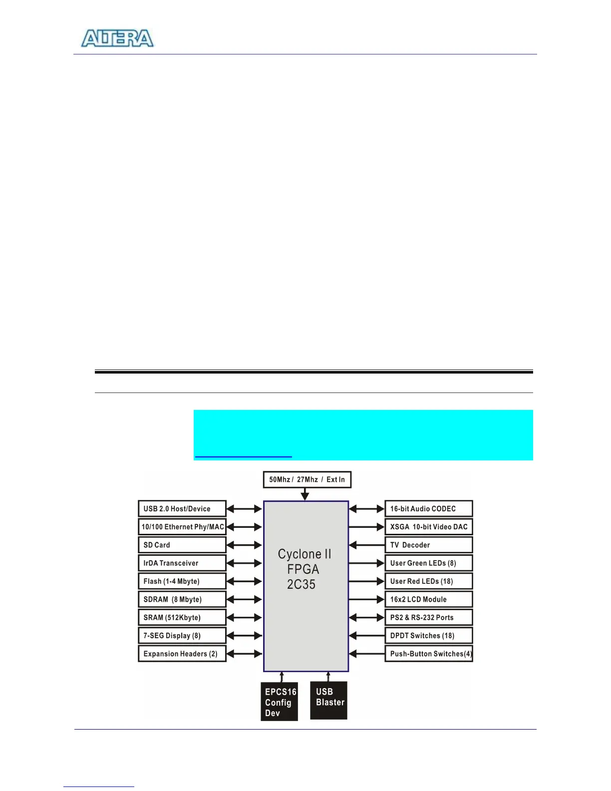
DE2 Block Diagram
Figure 2.2 shos a block diagram of the DE2 Board. The most recent
documentation for system can be obtained from the DE2 support website at:
http://de2.terasic.com