This lab demonstrates the audio quality of the DE2 Board by using its LINEIN,
LINEOUT, and microphone-in circuits in a Karaoke Machine Application
implemented on the DE2 board.
9-1
Design Descriptions
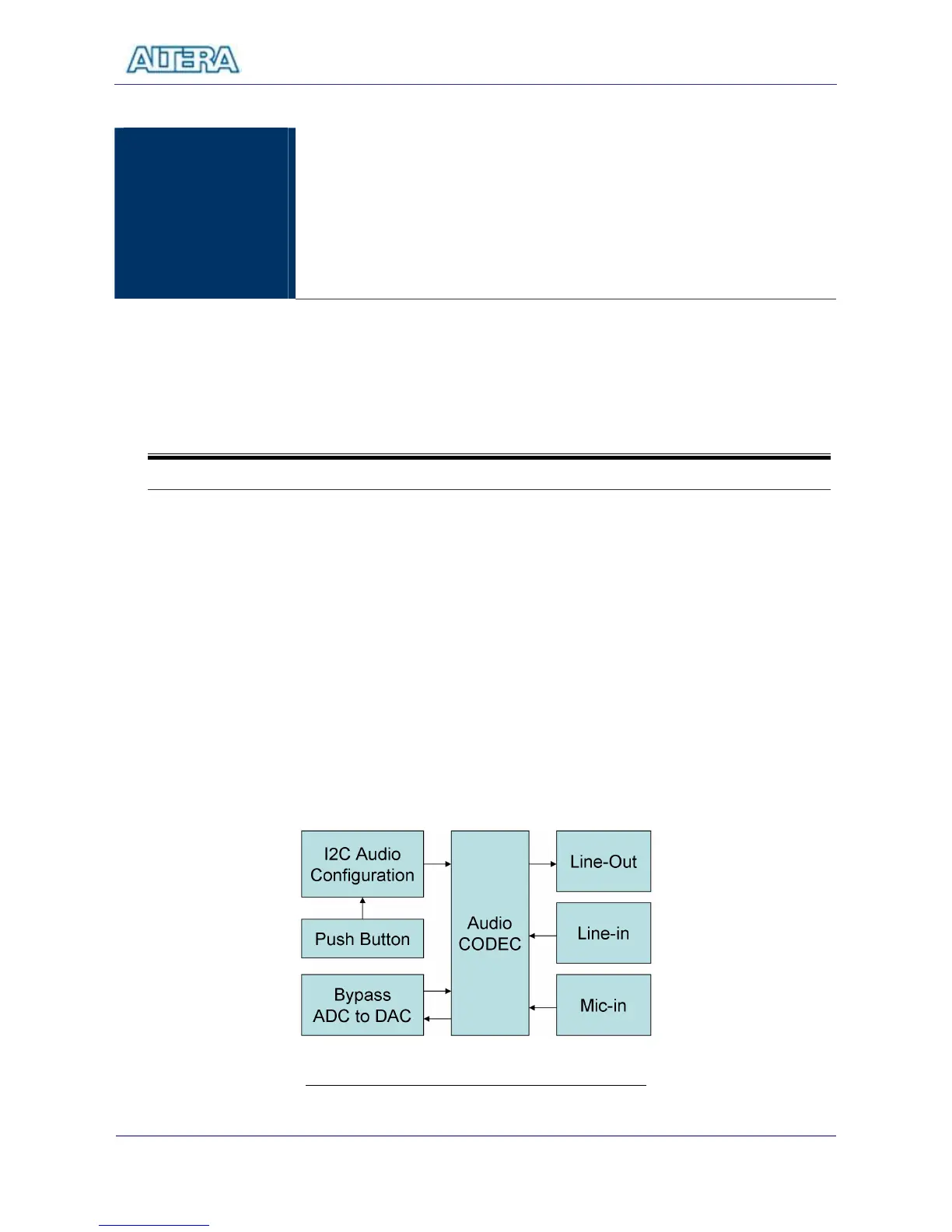
In this lab, we configure the audio CODEC in the master mode, where the audio
CODEC generates AD/DA serial bit clock (BCK) and the left/right channel clock
(LRCK) automatically. Therefore, users simply need to configure the sample rate
and gain of the audio CODEC. The data input from line-in is then mixed with the
microphone input and the result is sent to line-out, where users can use a
speaker to hear the sound.
The sample rate is set to 48Khz. When users press KEY0, FPGA will reconfigure
the gain of the audio CODEC via the I2C bus – it will circle through one of the ten
predefined gains (volume levels) whenever KEY0 is pressed.
Figure 9.1 The Block Diagram of a Karaoke Machine