26
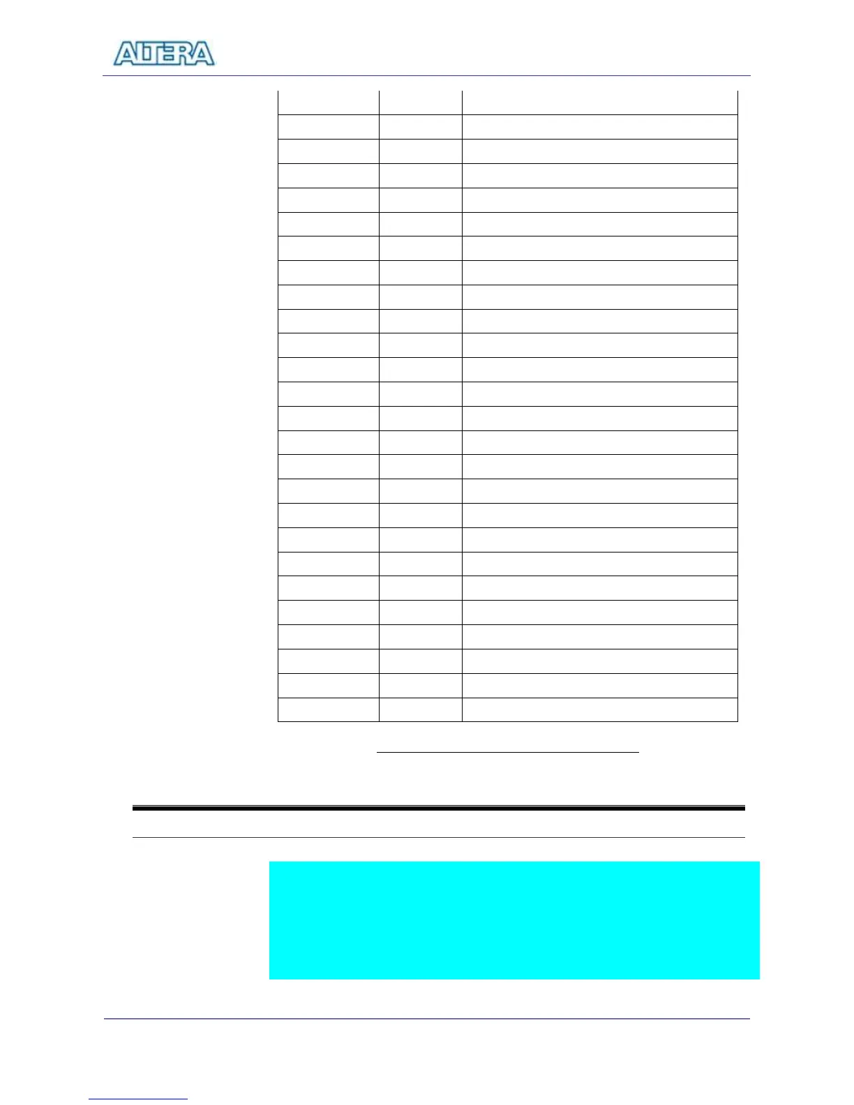
GPIO_1[10] PIN_N24 GPIO Connection 1[10]
GPIO_1[11] PIN_P24 GPIO Connection 1[11]
GPIO_1[12] PIN_R25 GPIO Connection 1[12]
GPIO_1[13] PIN_R24 GPIO Connection 1[13]
GPIO_1[14] PIN_R20 GPIO Connection 1[14]
GPIO_1[15] PIN_T22 GPIO Connection 1[15]
GPIO_1[16] PIN_T23 GPIO Connection 1[16]
GPIO_1[17] PIN_T24 GPIO Connection 1[17]
GPIO_1[18] PIN_T25 GPIO Connection 1[18]
GPIO_1[19] PIN_T18 GPIO Connection 1[19]
GPIO_1[20] PIN_T21 GPIO Connection 1[20]
GPIO_1[21] PIN_T20 GPIO Connection 1[21]
GPIO_1[22] PIN_U26 GPIO Connection 1[22]
GPIO_1[23] PIN_U25 GPIO Connection 1[23]
GPIO_1[24] PIN_U23 GPIO Connection 1[24]
GPIO_1[25] PIN_U24 GPIO Connection 1[25]
GPIO_1[26] PIN_R19 GPIO Connection 1[26]
GPIO_1[27] PIN_T19 GPIO Connection 1[27]
GPIO_1[28] PIN_U20 GPIO Connection 1[28]
GPIO_1[29] PIN_U21 GPIO Connection 1[29]
GPIO_1[30] PIN_V26 GPIO Connection 1[30]
GPIO_1[31] PIN_V25 GPIO Connection 1[31]
GPIO_1[32] PIN_V24 GPIO Connection 1[32]
GPIO_1[33] PIN_V23 GPIO Connection 1[33]
GPIO_1[34] PIN_W25 GPIO Connection 1[34]
GPIO_1[35] PIN_W23 GPIO Connection 1[35]
Table 3.8 Pin Assignment for expansion ports
3-9
Using the Serial Ports(RS232)
The DE2 Board uses the standard 9-pin D-SUB connector for RS-232
communications between PC and the board. The transceiver chip used is MAX232.
For detailed information on how to use the chip, users can refer to the spec under
C:\DE2\Datasheet\RS232. Figure 3.11 shows the related schematics. The pin
assignment of the associated interface is shown in Table 3.9.