Description
UART_RXD PIN_C25 UART Receiver
UART_TXD PIN_B25 UART Transmitter
Table 3.9 Pin Assignment for Serial Ports (RS232)
3-10
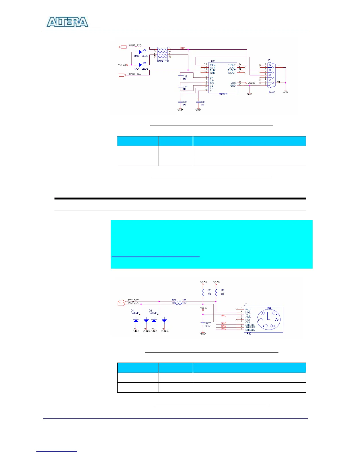
Using the Serial Ports(PS/2)
The DE2 Board offers standard PS/2 interface with a connector for a PS/2 keyboard
or mouse. Figure 3.12 shows the schematic of the PS/2 connector and circuits. For
how to use PS/2 mouse and keyboards, users can refer to
http://www.computer-engineering.org for more information. The pin assignment of
the associated interface is shown in Table 3.10.
Figure 3.12 PS/2 Port for Keyboard/Mouse Connections
Signal Name FPGA Pin No.