52
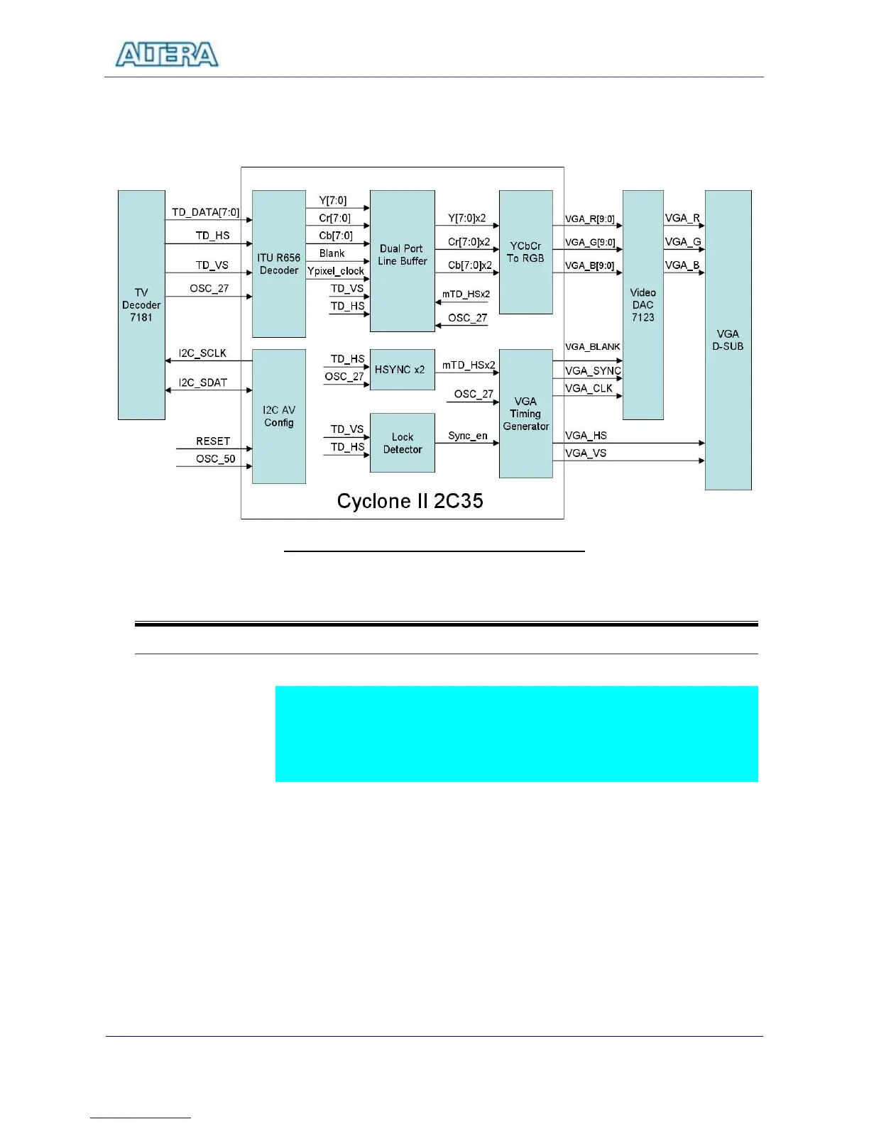
VGA Timing Generator block generates standard VGA sync signals – VGA_HS
and VGA_VS - to enable the display on a VGA monitor.
Figure 6.1 The block diagram of the TV Box design
6-2
Lab Setup and Instructions
Project Directory: C:\DE2\DE2_TV
Bitstream Used: C:\DE2\DE2_TV\DE2_TV.sof or DE2_TV.pof
Refer to Figure 6.2 and setup the lab according to the following steps:
Connect a DVD player’s Video output to the Video IN RCA Jack of the DE2
board.
Connect the VGA output of the DE2 board to a LCD/CRT Monitor.
Connect the audio output of the DVD player to the line-in port of the DE2
board and connect a speaker to the line-out port
Load the bitstream into FPGA
Now you can control your DVD players to play movie.
Press KEY0 to reset the circuit every time after power ON cycle.