15 / 44
NL
EN
Platform height 3.2 meter
11.
Place another platform on the 3rd rung of the frame,
staggered in relation to the platform below. Sit down on
the highest platform and attach the horizontal braces to
each side of the (rest) platform on the 4th rung above the
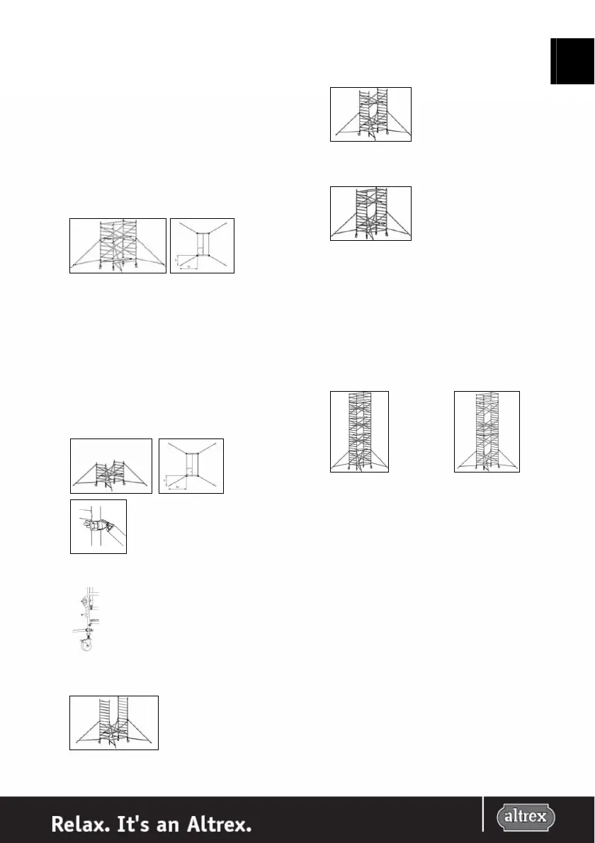
platform. Attach 4 stabilizers to the corners of the rolling
tower, at an angle of approximately 120° to the
longitudinal axis of the rolling tower. Attach the couplers
of the stabilizers to the uprights, under the 2nd and the
7th rungs of the base frame. Make sure that the end of
each stabilizer is in contact with the solid surface and
secure the stabilizer. Position the lowermost arm of the
stabilizer (approximately) horizontally, assemble the
stabilizers securely and check the angle of 120°.
Follow steps 7 to 10.
For further assembly to platform heights of 4.2 meter
follow steps 12 t/m 16.
12.
Attach 4 stabilizers to the corners of the rolling tower, at
an angle of approximately 120° to the longitudinal axis of
the rolling tower. Attach the couplers of the stabilizers to
the uprights, under the 2nd and the 7th rungs of the base
frame. Make sure that the end of each stabilizer is in
contact with the solid surface and secure the stabilizer.
Position the lowermost arm of the stabilizer
(approximately) horizontally, assemble the stabilizers
securely and check the angle of 120°.
13.
If needed (see ballast table at VI) attach the ballast to the 4
uprights of the base frame using the ballast holders.
Ballast holder (art.nr. 415277)
Ballast 5kg (art.nr. 415271)
14.
Stand on the platform and place two 7 rung frames on the
base frame of the rolling tower. Secure the base frames
with the locking pins.
15.
Then place two diagonal braces in a cross between the 2
nd
and the 6
th
rung on both sides of the frames which were
just placed. Place another platform on the 3
rd
rung of the
next frames, staggered in relation to the platform below.
16.
Sit down on the highest platform and attach the
horizontal braces to each side of the (rest) platform on
the 4
th
rung above the platform.
Repeat the steps 14, 15 and 16 until the desired platform
height (5,2 meter, 6,2 meter, 7,2 meter, 8,2 meter, 9,2
meter, 10,2 meter, 11,2 meter of 12,2 meter) is reached.
Then follow steps 7 to 10 for the placing of the guardrail
frames and the braces and then continue with step 17 in
order to prepare the tower for use. If applicable use a rope
for hoisting parts.
17.
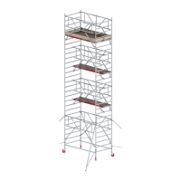
The platforms in between are now still in position to
ensure safety during assembly. The tower can be set up
in two configurations, 1 platform staggered every 2
meters (1/2 configuration) or two platforms next to each
other every 4 meters (2/4 configuration).
1/2 configuration 2/4 configuration
18.
The platforms in between, including the horizontal braces
have to be moved before the tower can be used. For the
adjusting of the platforms at different configurations
follow the diagrams for the order of assembly under VI.
The tower is now ready for use.
ROLLING TOWER 4200