8 / 44
EN
NL
EN 1004-3-8/8-XXXD
III.II Method of assembly rolling tower 4100
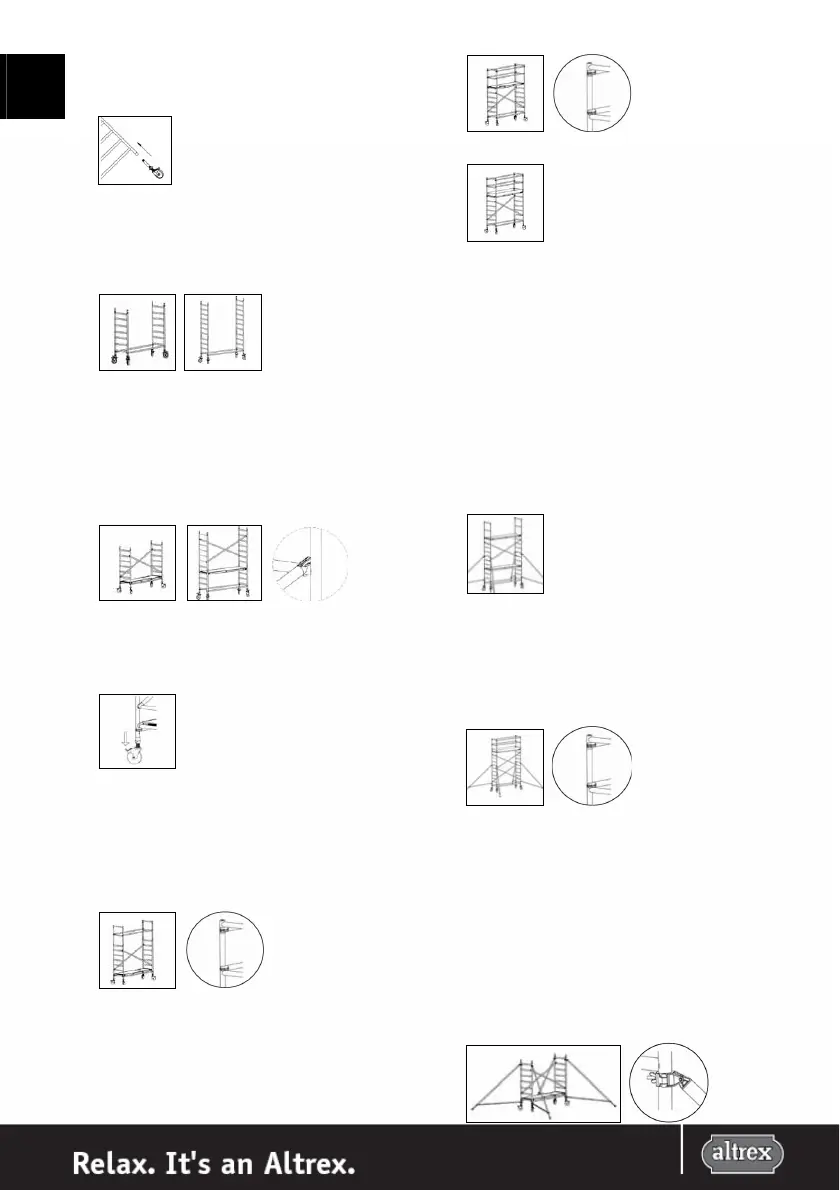
1.
Fit the wheels in the base frames or in the 4 rung frame in
the event of uneven platform heights.
2.
Connect the base frames by using 2 horizontal braces.
Assemble the horizontal braces, working from the inside
to the outside and under the 1
st
rung to the uprights of
the frames. In the event of uneven platform heights:
place two 7 rung assembly frames and secure with the
locking pins supplied.
3.
Then place two diagonal braces in a cross between the 2
nd
and the 6
th
rung of the base frame, one on the left and
one on the right side of the frame. Place a platform with
trapdoor on the first rung of the base frame. In the event
of uneven platform heights, place a platform with
trapdoor on the upper rung of the 4 rung frame. Stand on
the platform and then position two diagonal braces
between the 2
nd
and 6
th
rung of the 7 rung assembly
frame.
Align the wheels so that they point outwards. Lock the
wheels by pushing down the brake pedal. Then set the
base frame horizontally in the length and width direction
using a spirit level on the bottom rung and horizontal
brace.
For a configuration with a platform height of 2.2 meter
follow step 4, 5, and 6.
4.
Stand on the underlying platform and attach 2 guardrail
frames to the base frame of the rolling tower. Secure the
guardrail frames with the locking pins. Then, assemble
the knee braces, working from the inside to the outside,
against the uprights of the guardrail frames.
5.
Subsequently reposition the platform with trapdoor to the
7
th
rung of the (base) frame. Sit through the platform
trapdoor and assemble the top two guardrail braces
working from the inside to the outside against the
uprights of the guardrail frames.
6.
Attach the toe boards (see II.IX).
The rolling tower is now ready for use for a platform
height of up to 2.2 meter.
For a configuration with a platform height of 3.2 meter
follow step 7, 8, and 9.
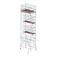
7.
From the platform, position the 2 guardrail braces on the
assembly frame. Secure the guardrail braces with the
locking pins. Position a platform with trapdoor on the 7th
rung of the assembly frame. Assemble the 4 stabilizers on
the corners of the tower at an angle of about 120° to the
longitudinal access of the tower. Attach the couplers of
the stabilizers to the uprights under the 2
nd
and 7
th
rungs.
Make sure that the end of each stabilizer is in contact
with the solid surface and secure the stabilizer. Position
the lower arm of the stabilizer approximately horizontal,
secure the coupling and check the 120° angle.
8.
Sit through the platform trapdoor and assemble the
guardrail braces working from the inside to the outside
against the uprights of the guardrail braces. Attach the
toe boards(see II.IX).
9.
The lower platform must be removed before the tower
can be used. Then place 2 diagonal braces in a cross
between the 2
nd
and 6
th
rung.
The tower is now ready for use.
Further assembly of 7 rung frames to a platform height of
4.2 meter.
10.
Assume the base frame described in step 3. Attach the 4
stabilizers to the corners of the tower, at an angle of
approximately 120° to the longitudinal axis of the tower.
Attach the couplers of the stabilizers to the uprights
under the 2
nd
and the 7
th
rung of the frames. Make sure
that the end of each stabilizer is in contact with the solid
surface and secure the stabilizer. Position the lowermost
arm of the stabilizer approximately horizontally,
assemble the stabilizers securely and check the angle of
120°.