3. PANEL DESIGN
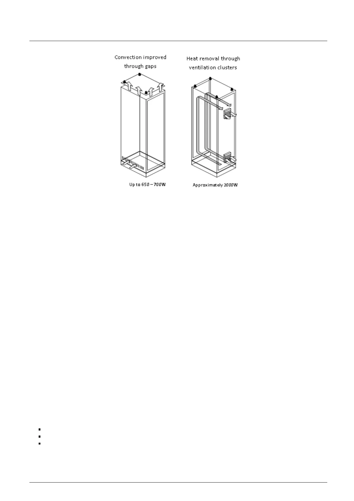
Figure 34: Example of Heat Flow – Open Installation
3.3. Electrical Design
3.3.1. General Information
The programmable controllers are manufactured according world standards, which establish the acceptable levels of room
conditions and noise often found in industrial processes. It’s also fundamental that the installation of these products follow
the designing rules established by installation standards. Troubles caused by electromagnetic interference (EMI), such as
communication failures, program execution failures, analog variables noise and even program loss, can be caused by a deficient
installation or electrical design.
The electrical design of the Altus PLCs must respect the IEEE 518/1977 standard, "Guide for Installation of Electrical
Equipment to Minimize Electrical Noise Inputs to Controller External Sources". Following, the most important subjects are
described.
3.3.2. Panel Supply
The control system supply must have a general switch. It’s recommended the use of connectors for the panel general supply
with integrated fuses, as the installation of a 127 Vac or 220 Vac outlet, for the programming terminal. It’s important that this
outlet has a ground pin, as the programming terminal must be, mandatory, grounded. All panel outlets must have its voltages
levels identified.
3.3.3. Panel Cables Distribution
The way the signal and supply cable are distributes is, no doubt, one of the most important points in the installation of
programmable controllers. The correct distribution of the cables inside the panel and the correct grounding of the devices
guarantee the electromagnetic compatibility (EMC) of the installation.
It’s important the panel electrical supplies are correctly distributes, through distribution bars or connectors.
From this general distribution points, a cable is taken for each specific point to be fed. Local jumpers in the modules supply
must be avoided, decreasing the high current loaded cables length.
In order to increase the equipment performance, it’s necessary to separate the circuits regarding their type, to decrease
electromagnetic interference, as follows:
AC supplied circuits and AC and DC loads activation
Low current (less than 1A) digital inputs and outputs
Analog circuits and communication
These circuits must be distributed preferentially in separate chutes or avoiding they are placed parallel to each other. The
minimum distance of 150 mm is recommended between all I/O signals and supply voltages higher than 500V.
39