4. INSTALLATION
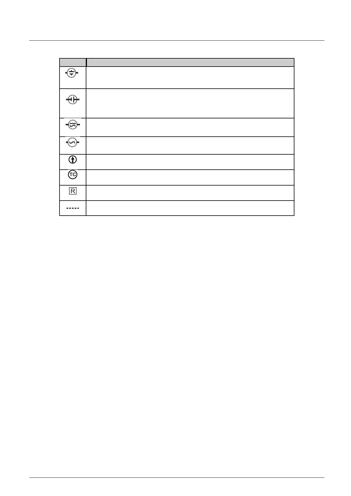
Symbol Meaning
This symbol indicates a direct current power supply source. On this symbol the power
supply polarity isn’t specified. This means the user can choose the polarity according
to his demands. The voltage must be compatible with the module characteristics.
This symbol indicates a direct current power supply source. On this symbol the power
supply polarity is specified according to the inner circle bar. The bigger bar indicates
the positive pole while the smaller bar indicates the negative pole. The voltage must
be compatible with the module characteristics.
This symbol indicates a power supply source which can be direct current or alternate
current. The voltage must be compatible with the module characteristics.
This symbol indicates an alternate current power supply source. The voltage must be
compatible with the module characteristics.
This symbol indicates a direct current source. On this symbol the conventional current
flux is indicated by the direction of the arrow inside the circle.
This symbol indicates a thermocouple sensor connected in an analog input of a Nexto
Series module.
This symbol indicates a resistance or a RTD sensor (Resistance temperature detector)
connected in an analog input of Nexto Series module.
This symbol indicates that exist options to connect an input or output, according with
the Nexto Series module characteristics.
Table 8: Installation Diagram Symbols
4.2.4.5.3. Label insertion and removal
To add the identification number and module description it’s necessary to remove the I/O module frontal label as shown
on figure below. This figure shows an I/O module frontal cover which uses one slot in the rack. The same procedure must be
executed for modules that use two slots.
61



 To Next Page