3. PANEL DESIGN
3.3.4. Panel Illumination
It’s very important to install illumination inside the panel, activated through a switch, to facilitate its operation.
It’s recommended the illumination to be based on incandescent bulbs, as fluorescent luminaries may cause undesirable
interference. If the latter are used, the following precautions must be made to reduce interference:
Grounded metallic grid must be installed between the luminary and the panel, in order to reduce the noise emission
The luminary supply cables must be shielded
The switch must be protected by a metallic box and a filter must be placed in the supply network, next to the luminary
3.3.5. Grounding
It is necessary a group of general connectors or ground bar in the panel, where all the power sources and modules grounding
will be made. This bar must be connected to a low resistance ground.
3.3.6. Electromagnetic Interference
The electromagnetic interference (EMI) is responsible for the great majority of troubles found in the installed equipment.
These problems can be reduced significantly if the due precautions are taken in the panel designing phase:
Distribute and place the cable in the chutes, avoiding mix supply cables with signal cables
Inactive metallic parts must be grounded
In case there’re noise emitter elements, it’s recommended the use of shields
A filter must be used in the panel supply cable
3.3.7. Shield
Strong EMI sources (transformers, motors, and high current or voltage cables) placed inside the panel must be covered by
grounded metallic plates, when installed less than 50 cm from the PLC electronic parts. Cables which cross the shielded parts
must be shielded too or filtered.
The shielded cables within the panel must be grounded according instructions of each device.
3.3.8. Noise Suppressors
It’s extremely important the connections of noise suppressors straight in every inductive loads (relays, contactors, solenoids,
etc.) activated or not by the PLC. The inductive loads activation generates strong electrical noises which may go over the limits
established by standards. These noises, if not mitigated in its origin, might reach the PLC jeopardizing its functioning.
The protection circuits must be connected close to the load, as a rule, they mustn’t be more than 0.5 meters apart. In case
of resistive loads (incandescent bulbs, signal LEDs, heating resistances, etc.), the use of such devices isn’t need it.
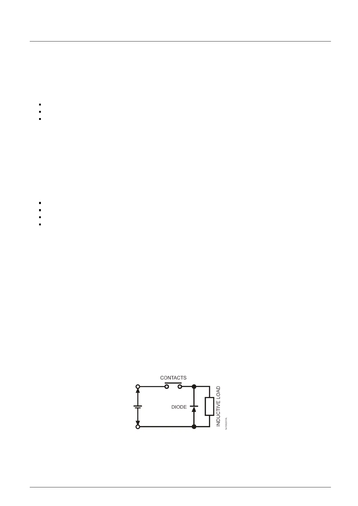
3.3.8.1. Circuit with Diode
This is the most efficient way to limit the inductive circuit voltage on the off moment. However, it can cause troubles as it
slow down the off time in case the load is, for instance, a contactor or a solenoid.
Figure 35: Diode circuit
The circuit can be used only for DC voltages and its reverse voltage must be higher than the power source and the current
at least the same as the load.
40



 To Next Page