10
8 Condensate Drain Lines
The coil drain pan has a primary and a secondary drain
with 3/4” NPT female connections. The connectors required
are 3/4” NPT male, either PVC or metal pipe, and should
be hand tightened to a torque of no more than 37 in-lbs. to
prevent damage to the drain pan connection. An insertion
depth of approximately 3/8” to 1/2” (3-5 turns) should be
expected at this torque.
1. Ensure drain pan hole is not obstructed.
2. To prevent potential sweating and dripping on to
condensate drain line located inside the building. Use
A secondary condensate drain connection has been provided
for areas where the building codes require it. Pitch all drain
lines a minimum of 1/4” per foot to provide free drainage.
Provide required support to the drain line to prevent bowing.
If the secondary drain line is required, run the line separately
from the primary drain and end it where condensate
discharge can be easily seen.
NOTE: Water coming from secondary line means the coil
primary drain is plugged and needs immediate attention.
CAUTION
Insulate drain lines located inside the building or above
condensate trap to ensure proper drainage.
NOTE: When units are installed above ceilings, or in other
drain pan under the coil cabinet enclosure.
as close as is practical to the evaporator coil. See Figure 12
NOTE: Units operating in high static pressure applications
is shown in Figure 12 to allow proper drainage and prevent
Air Handler
2.75" MI
POSITIVE LIQUID
SEAL REQUIRED
AT TRAP
Connection
2" MIN.
Figure 12
NOTE: Trapped lines are required by many local codes. In
the absence of any prevailing local codes, please refer to the
requirements listed in the Uniform Mechanical Building Code.
A drain trap in a draw-through application prevents air from
being drawn back through the drain line during fan operation
thus preventing condensate from draining, and if connected
to a sewer line to prevent sewer gases from being drawn
into the airstream during blower operation.
Use of a condensate removal pump is permitted when
necessary. This condensate pump should have provisions
occur. A trap must be installed between the unit and the
condensate pump.
IMPORTANT NOTE: The evaporator coil is fabricated
with oils that may dissolve styrofoam and certain types of
contain any of these materials.
initial installation and at the beginning of the cooling season.
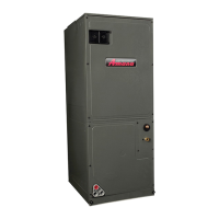
9 Ductwork
This air handler is designed for a complete supply and return
ductwork system.
CAUTION
To ensure correct system performance, the ductwork is to
be sized to accommodate 350-450 CFM per ton of cooling
with the static pressure not to exceed 0.5” in w.c. Refer to
ACCA Manual D, Manual S and Manual RS for information
on duct sizing and application. Flame retardant ductwork
is to be used and sealed to the unit in a manner that will
prevent leakage.
NOTE:
an L-shaped sheet metal supply duct without any outlets or
registers located directly below the heater.
 Loading...