14
12.4 Electrical Connections – Supply Voltage
CAUTION
FIRE HAZARD!
IMPORTANT NOTE: USE COPPER CONDUCTORS ONLY
FROM DISCONNECT OR ELECTRICAL PANEL TO THE
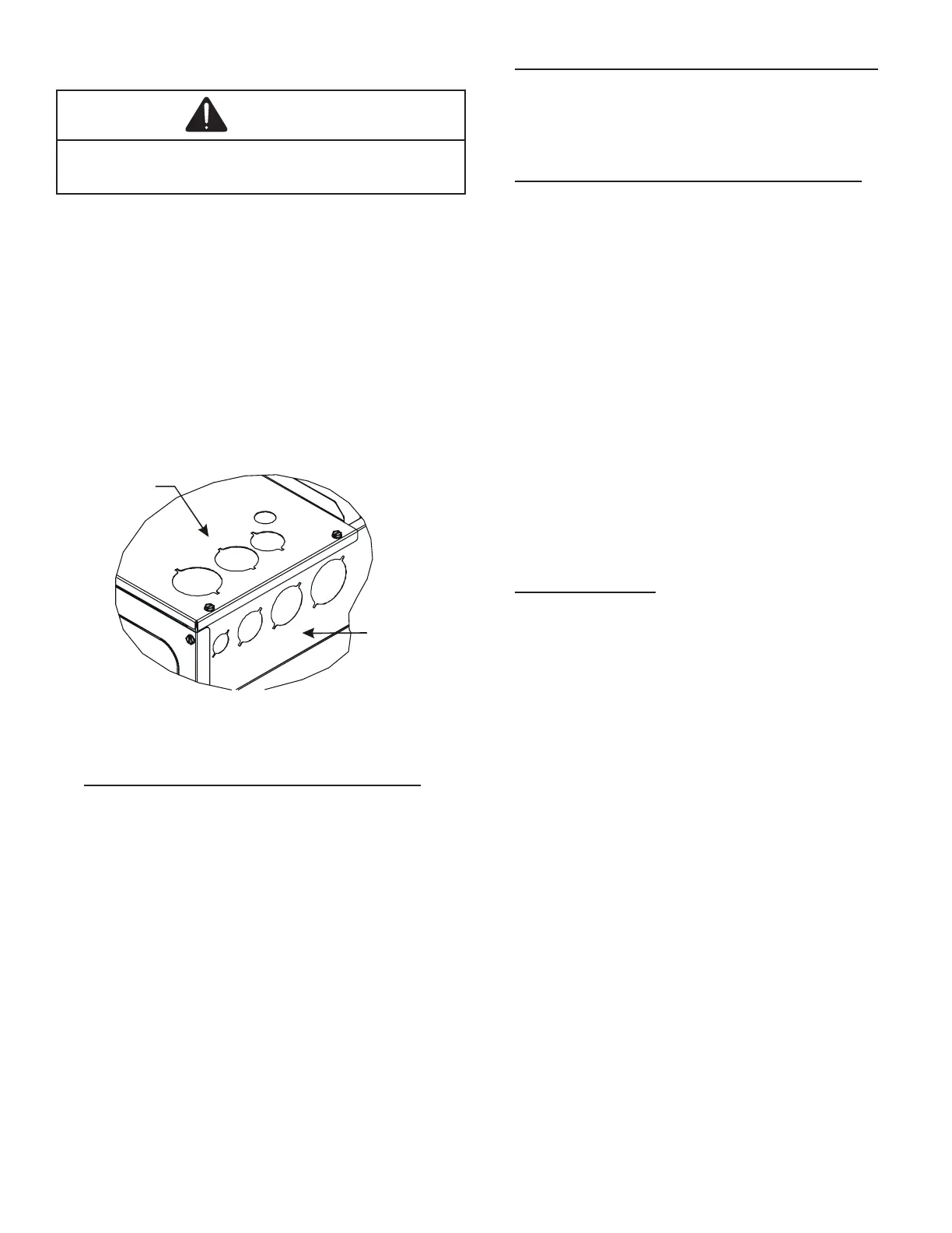
Knockouts are provided on the air handler top panel and
sides of the cabinet to allow for the entry of the supply voltage
conductors, as shown in Figure 13. If the knockouts on the
cabinet sides are used for electrical conduit, an adapter ring
must be used in order to meet UL1995 safety requirements.
An NEC or CEC approved strain relief is to be used at this
entry point. Some codes/municipalities require the supply
wire to be enclosed in conduit. Consult your local codes.
Side of
Cabinet
Top of
Cabinet
KNOCK-OUT FOR ELECTRICAL CONNECTIONS
Figure 13
12.4.1 Air Handler Only (Non-Heat Kit Models)
The building supply connects to the stripped black
and red wires contained in the air handler electrical
compartment cavity. A ground screw is also contained
in this area. Attach the Supply wires to the air handler
conductors as shown in the unit wiring diagram using
appropriately sized solderless connectors or other NEC
or CEC approved means.
12.4.2 Air Handler - Non-Circuit Breaker Heat Kits
A terminal block is provided with the HKS kit to attach
the power supply and air handler connections. Follow
the HKS Installation Manual and wiring diagram for
complete wiring details.
12.4.3 Air Handler With Circuit Breaker Heat Kit
The air handler has soft plastic cover on the upper
access panel and can be removed to allow the heater
kit circuit breaker to be installed. The circuit breakers
have lugs for power supply connection. See the HKS
Installation Instructions for further details.
12.5 Low Voltage Connections
Several combinations of low voltage schemes are
possible, depending on the presence of a heat kit and
whether the heat kit is single-stage or multi-stage,
whether the outdoor section is an air conditioner or heat
pump, and whether the outdoor section is single-stage
or two-stage. The 24V-control voltage connects the air
handler to the room thermostat and condenser. Low
voltage wiring must be copper conductors. A minimum
of 18AWG must be used for installations up to 100 feet.
Low voltage wiring must be connected through the
Wiring” section of this manual for typical low voltage
wiring connections.
12.5.1 Thermostats
Second-stage heat can be accomplished by a multi-
stage heating thermostat or the addition of an outdoor
thermostat as shown in wiring schematics on page 19.
Follow the thermostat manufacturer’s instructions for
installation.
12.6 Speed Tap Adjustment
ARUF**14** air handlers have multi-speed PSC motors.
The color of the wire coming from the motor to the
speed the motor will operate. Black wire is high speed,
blue wire is medium speed and red wire is low speed. To
terminal on the control board, and swap it with the wire
desired speed.
 Loading...