6
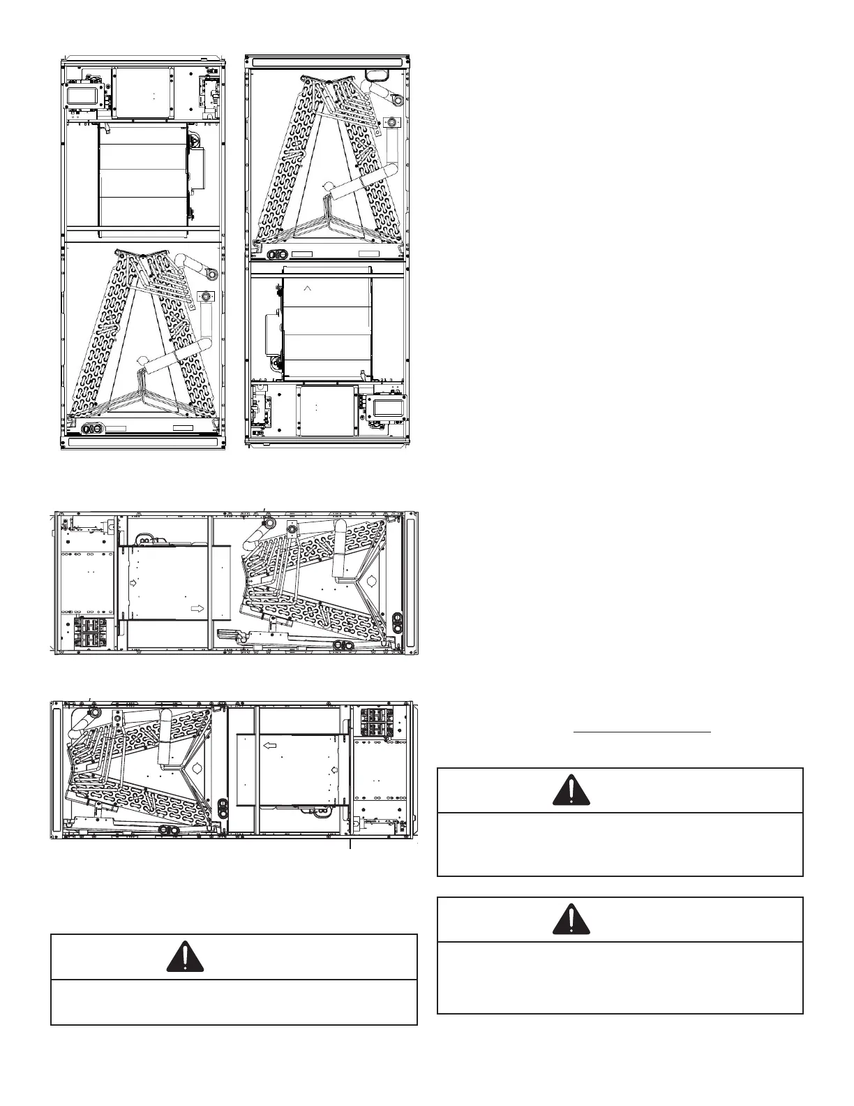
UPFLOW DOWNFLOW
Figure 2 Figure 3
HORIZONTAL LEFT
Figure 4
HORIZONTAL RIGHT
Figure 5
7 Refrigerant Lines
WARNING
NOTE: Refrigerant tubing must be routed to allow adequate
access for servicing and maintenance of the unit.
Do not install the air handler in a location that violates the
instructions provided with the condenser. If the unit is located
in an unconditioned area with high ambient temperature and/
or high humidity, the air handler may be subject to nuisance
sweating of the air handler cabinet. On these installations,
recommended.
7.1 Tubing Size
the condenser/heat pump.
7.2 Tubing Preparation
All cut ends are to be round, burr free, and clean.
Failure to follow this practice increases the chances for
refrigerant leaks. The suction line is spun closed and
requires tubing cutters to remove the closed end.
NOTE: To prevent possible damage to the tubing joints, do
Always use clean gloves when handling coil assemblies.
7.3 Special Instructions
Units without a factory installed TXV come equipped
most installations with matching applications, no
may be required. See the piston kit chart (provided in
the literature packet) or consult your local distributor for
body on the indoor coil before installing the coil and use
the procedure in section 7.4.
NOTE: The use of a heat shield is strongly recommended
when brazing to avoid burning the serial plate or the
Heat trap or wet rags must be used
to protect heat sensitive components such as service
valves and TXV valves sensing bulb.
WARNING
CAUTION
 Loading...