8
7.4 Tubing Connections for Flowrator Model
1. Loosen the 13/16 nut 1 TURN ONLY to allow high
pressure tracer gas to escape. No gas indicates a
possible leak.
2. After the gas has been expelled, remove the nut and
discard the black or brass cap plastic seal.
3.
for the outdoor unit being installed and then replace the
piston (changing size, if needed). See piston kit chart in
the literature kit for appropriate piston size.
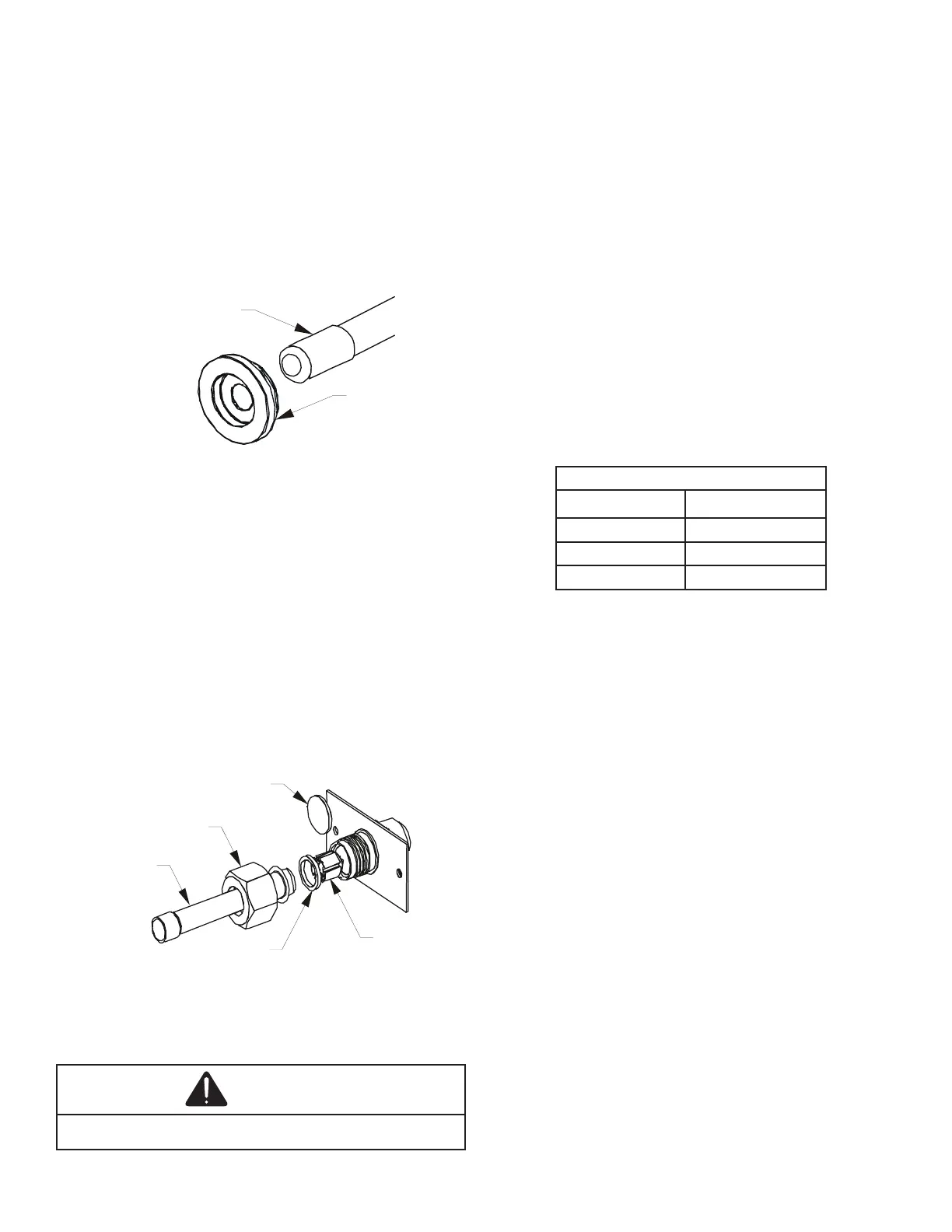
4. Remove the spin closure on the suction line using a
tube cutter and deburr the tube.
RUBBER
GROMMET
SUCTION LINE
WITH SPIN CLOSURE
SUCTION SPUN END AND GROMMET
Figure 10
5. Insert the suction line into the connection, slide the
insulation and the rubber grommet at least 18” away
from the braze joint.
6. Remove the tailpiece clamped to the exterior of the
cabinet or in the literature kit packet and slide the
7. Braze tailpiece to the line set liquid tube and braze
suction line connection. Quench all brazed joints with
a damp rag upon completion of brazing. Do not allow
water to enter the inside of the tubing.
AFTER THE TAILPIECE HAS COOLED
13/16 nut.
WHITE
TEFLON SEAL
PISTON
TAILPIECE
13/16” NUT
PLASTIC or BRASS CAP
TAILPIECE JOINT
Figure 11
9. Torque the 13/16 nut to 7-25 ft-lbs. or tighten 1/6 turn.
CAUTION
7.5 Tubing Connections for TXV Models
TXV models come with factory installed TXV with the
bulb pre-installed on the vapor tube.
1. Remove refrigerant tubing panel or coil (lower) access
panel.
2.
indicates possible leak.
3. Replace the refrigerant tubing panel.
4. Remove the spin closure on both the liquid and suction
tubes using a tubing cutter.
5. Insert liquid line set into liquid tube expansion and slide
grommet about 18” away from braze joint.
6. Insert suction line set into suction tube expansion and
slide insulation and grommet about 18” away from
braze joint.
7. Braze joints. Quench all brazed joints with water or a
wet rag upon completion of brazing.
7.6 ASPT**14** Models with Non-Adjustable TXV
ASPT air handlers equipped with Parker non-adjustable
TXV should be charged by subcooling only.
Models
ASPT25B14**A SPT47D14**
ASPT29B14**A SPT47C14**
ASPT37B14**A SPT49D14**
ASPT37C14**A SPT59C14**
Table 4
See section 7.7 for detailed information on adjusting the
thermal expansion valve.
7.7 Thermal Expansion Valve System Adjustment
Run the system at Cooling for 10 minutes until refrigerant
pressures stabilize. Use the following guidelines and methods
to check unit operation and ensure that the refrigerant charge
is within limits. Charge the unit on low stage.
1. Purge gauge lines. Connect service gauge manifold to
base-valve service ports.
2. Temporarily install a thermometer on the liquid line at the
liquid line service valve and 4-6” from the compressor on
the suction line. Ensure the thermometer makes adequate
contact and is insulated for best possible readings. Use
liquid line temperature to determine subcooling and vapor
temperature to determine superheat.
3. Check subcooling and superheat. Systems with TXV
application should have a subcooling of 7 to 9ºF and
superheat of 7 to 9 ºF.
a. If subcooling and superheat are low, adjust TXV to
7 to 9 ºF superheat, then check subcooling.
NOTE: To adjust superheat, turn the valve stem
clockwise to increase and counter clockwise to
decrease.
b. If subcooling is low and superheat is high, add
charge to raise subcooling to 7 to 9ºF then check
superheat.
c. If subcooling and superheat are high, adjust TXV
valve to 7 to 9 ºF superheat, then check subcooling.
 Loading...