5
6.2 Horizontal Left Installation (Figure 4)
Install unit as shown in Figure 4.
Drain port labeled (B) in Figure 1 is the primary drain
for this application and condensate drain line must
be attached to this drain port. Drain port (b) is for the
secondary drain line (if used).
Remove red plugs from side drain pan before connecting
condensate drain pipes. Use removed plug to close
drain ports on vertical drain pan.
6.3 Horizontal Right Installation (Figure 5)
1. Before inverting the air handler, remove blower access
panel and coil access panel. The coil access panel and
tubing panel may remain screwed together during this
procedure. Remove and retain the seven (7) screws
securing the coil access panel to the cabinet and the
six (6) screws securing the blower access panel to the
cabinet.
2. Slide the coil assembly out from the cabinet. Use the
drain pan to pull the assembly from the cabinet.
NOTE: Do not use manifolds, copper lines, or the
may result in braze joint damage and leaks.
3. Removal of the center support is required on units
with 21” wide cabinet. Remove and retain the two (2)
screws that secure the center support to the cabinet.
Remove the center support.
4.
5. Remove side drain pan extension in all models except:
ARUF47D14**, ARUF61D14**, ASPT61D14**, and
ASPT49D14**.
6. Using the drain pan to hold the coil assembly, slide the
brackets as shown in Figure 7.
7. Reinstall the center support (if removed) using the two
(2) screws removed in Step 5.
8. Reinstall the coil access panels and reinstall blower
access panel removed in Step 1 as shown in Figure 9.
9. Drain Connections for Horizontal Right Installation
a. Drain port labeled (B) in Figure 1 is the primary
drain for this application and condensate drain line
must be attached to this drain port. Drain port (b) is
for the secondary drain line (if used).
b. Remove red plugs from side drain pan before
connecting condensate drain pipes. Use removed
plug to close drain ports on vertical drain pan.
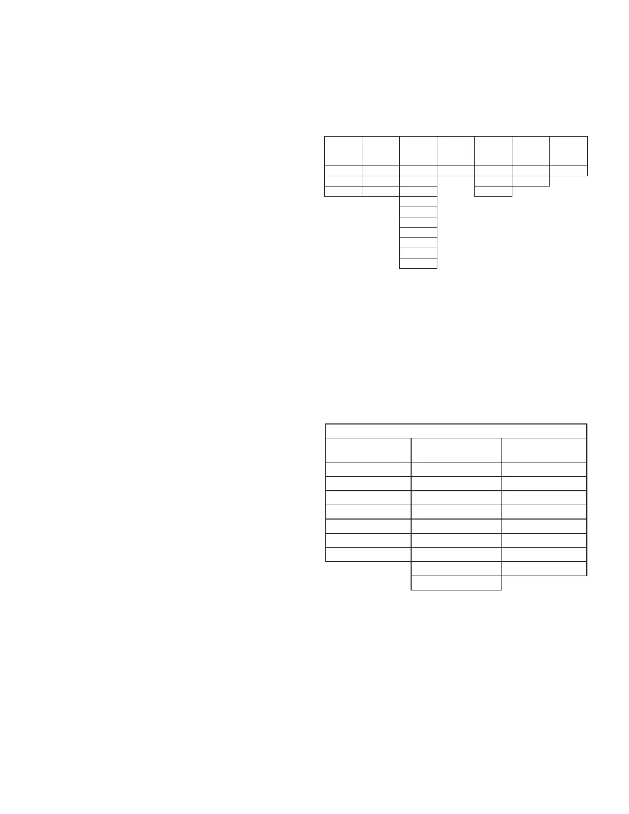
Horizontal Left Installation - Humid Environments
In applications where the air handler is installed in the
horizontal left position, and the return air environment see
humidity levels above 65% relative humidity coupled with
total external static levels above 0.5” e.s.p., a condensate
found in Table 2.
CMK0008
Condensate
Kit
CMK0009
Condensate
Kit
CMK0010
Condensate
Kit
CMK0011
Condensate
Kit
CMK0012
Condensate
Kit
CMK0013
Condensate
Kit
CMK0014
Condensate
Kit
ARUF25B14 ARUF31B14 ARUF37C14 ARUF47D14 ARUF61D14 ASPT33C14 ASPT49C14
ARUF29B14 ASPT29B14 ARUF37D14 ASPT49D14 ASPT39C14
ASPT25B14 ASPT37B14 ARUF43C14 ASPT61D14
ARUF43D14
ARUF49C14
ARUF49D14
ASPT37C14
ASPT47C14
ASPT47D1 4
ASPT59C14
CONDENSATE KIT
Table 2
Downow Installation - Humid Environment
The DFK kit is not supplied with the air handler and is available
through your local distributor. See Table 3 for the correct DFK
and follow the instructions provided for installation.
Refer to Figure 6 and 7 for the location of the components
referenced in the following steps.
DFK-B
DOWNFLOW KIT
DFK-C
DOWNFLOW KIT
DFK-D
DOWNFLOW KIT
ARUF25B14** ARUF37C14** ARUF37D14**
ARUF29B14** ARUF43C14** ARUF43D14**
ARUF31B14** ARUF49C14** ARUF47D14**
ASPT25B14** ASPT33C14** ARUF49D14**
ASPT29B14** ASPT37C14** ARUF61D14**
ASPT35B14** ASPT39C14** ASPT61D14**
ASPT37B14** ASPT47C14** ASPT47D14**
ASPT49C14** ASPT49D14**
ASPT59C14**
MODEL LIST FOR DOWNFLOW KIT
DOWNFLOW KIT
Table 3
 Loading...