4
5.6 Access
This unit should be installed in a manner so that it is not
accessible to the public.
6 Installation Location
NOTE: These air handlers are designed for indoor installation
only at a max altitude of 10,500 feet above sea level or a min
altitude of -184 feet below sea level.
If the unit is located in an unconditioned area with high
ambient temperature and/or high humidity, the air handler
may be subject to nuisance sweating of the casing. On
vapor barrier is recommended. A secondary drain pan below
the unit is also recommended to protect the installation site.
shown in Figures 2, 3, 4 and 5. The unit may be installed
sections for more information).
6.1 Upow and Downow Installation (Figure 2 & 3)
1. Remove blower access panel and coil access panel.
The coil access panel and tubing panel may remain
screwed together during this procedure. Remove and
retain the seven (7) screws securing the coil access
panel to the cabinet and the six (6) screws securing the
blower access panel to the cabinet.
2. Slide the coil assembly out from the cabinet. Use the
drain pan to pull the assembly from the cabinet.
IMPORTANT: Do not use manifolds, copper lines, or
so may result in braze joint damage and leaks.
3. Removal of the center support is required on units
with 21” wide cabinet. Remove and retain the two (2)
screws that secure the center support to the cabinet.
Remove the center support.
a. Using the drain pan to hold the coil assembly, slide
the coil assembly back into the cabinet.
b. Reinstall the center support (if removed) using the
two (2) screws removed in Step 3.
c. Reinstall the coil access panels and reinstall
blower access panel removed in Step 1 as shown
in Figure 8.
a.
b. Using the drain pan to hold the coil assembly, slide
the coil assembly back into the cabinet on the
c. Reinstall the center support (if removed) using the
two (2) screws removed in Step 3.
d. Reinstall the coil access panels and reinstall
blower access panel removed in Step 1 as shown
in Figure 9.
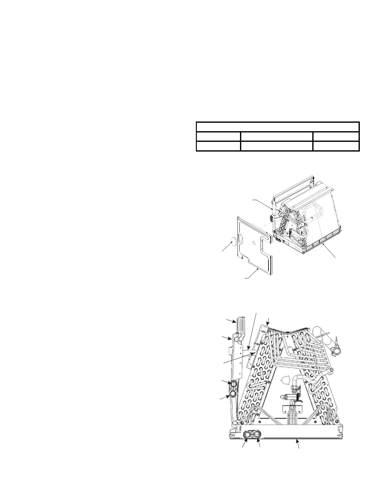
Side Drain Pan and Extension Removal Instructions
Refer to Figure 1, remove the two (2) screws that secure
the drip shield support brackets to the condensate collectors
(front and back). Unsnap the side drain pan from the bottom
drain pan using a screwdriver or any small lever. The side
drain pan, drip shield brackets and the drain pan extension
may now be removed. From Figure 1, drain port labeled (A)
is the primary drain for this application and condensate drain
line must be attached to this drain port. Drain port (a) is for
the secondary drain line (if used). When the side drain pan is
removed, the drain port opening in the access panel must be
covered by the accessory drain port plug (DPK1) as shown
in Figure 1.1.
DPK1 All Models
DRAIN PORT PLUG KIT
Table 1
SIDE DRAIN PAN
DPK1 DRAIN PLUG
COIL ACCESS PANEL
DRAIN PAN
Figure 1.1
rip Pan
xtension
Side
Drain
Pan
Screw
B
b
A
Main Drain Pan
Drip Shield Bracket
Drip Shield
Pna
SIDE DRAIN PAN REMOVAL
Figure 1
 Loading...