Layout and function
D9 BAH0041-4 08.18
91
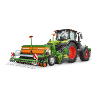
5.24.3.1 Lay shaft coupling, mechanically actuated
The lay shaft coupling (Fig. 104/1) is actuated by a rod (Fig. 104/2), as soon as the divider wheel (Fig.
104/3) shows the number "0" on the control box.
Fig. 104
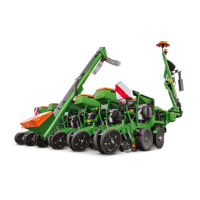
The tramline number on the divider wheel (Fig.
105/2) on the control box is clearly visible from
the tractor seat.
The operating lever (Fig. 105/1) is used to switch
the divider wheel.
The rope (Fig. 105/3) can be used to make cor-
rections from the tractor seat if the divider wheel
shows the wrong tramline number.
Fig. 105



 To Next Page