Installation 2-13
Sample System
Sample Tap
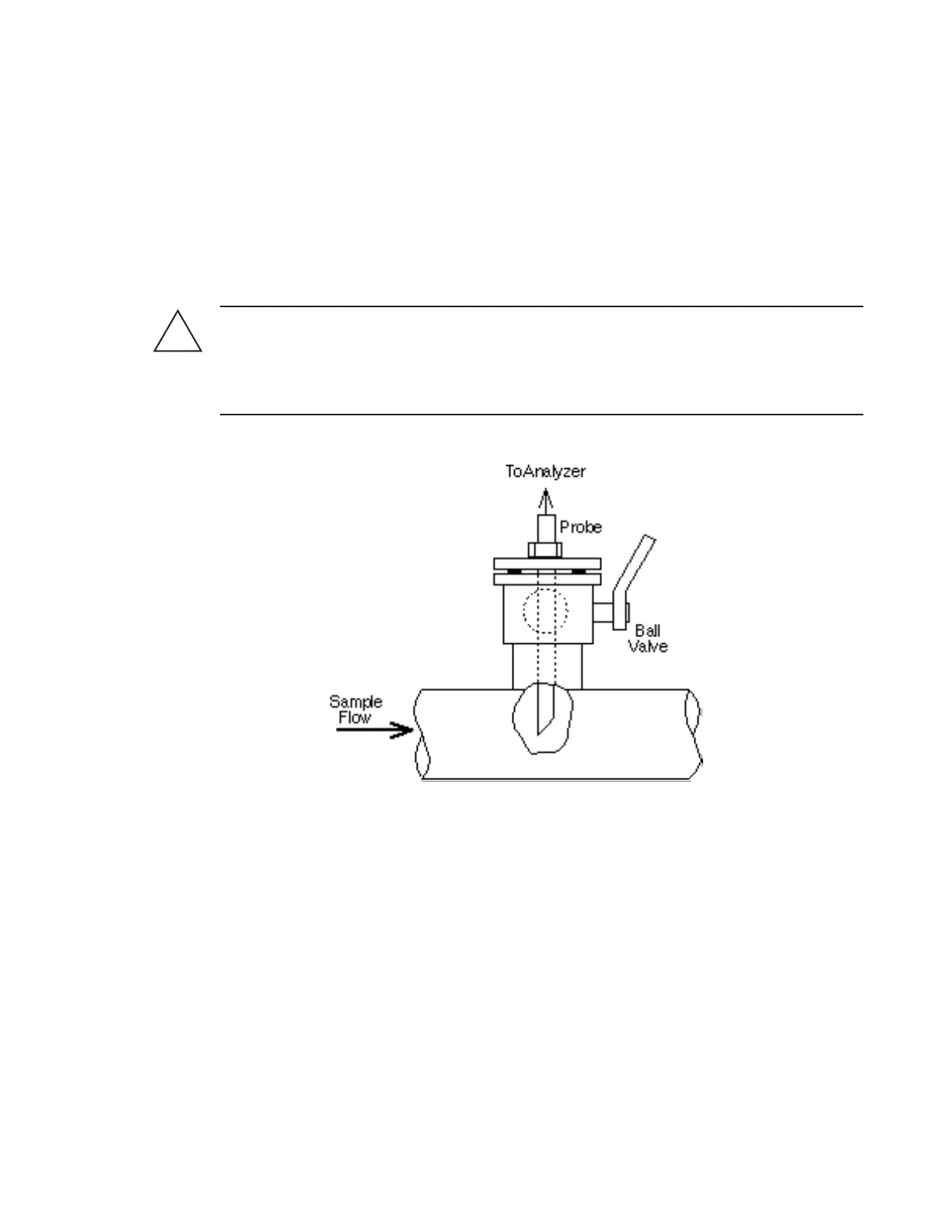
To ensure sample is free of contaminants from the walls of the sample pipeline, a probe extend-
ing into the pipe is recommended. The probe tip should be cut to a 45° angle and located about
20-30% into the pipe ID. Mount the probe through a ball valve (shut-off valve) on a horizontal
section of the pipe as shown in Figure 8.
The sample gas, or gasses to be monitored by the Analyzer may be toxic, corrosive, and / or
flammable. AMETEK strongly recommends that trained service personnel use proper protec-
tive equipment including air breathing apparatus, eye protection, and skin protection when-
ever the gas line(s) or Field Unit are accessed for installation or maintenance.
Figure 8: Typical Probe Installation
Sample Pressure, Temperature, and Flow Rate
A pressure reducer/regulator should be installed near the sample tap. Variations in flow of 10
percent will not affect instrument accuracy. Nominal sample pressure to the system should be
520 kPa (75 psi) gauge with a minimum pressure of 200 kPa (30 psi) gauge. Temperature of the
incoming sample gas should not exceed the analyzer cell temperature of 60°C (140°F). Sample,
reference, and moisture generator flow rates through the cell are set to 250 cc/min (at 2 atm) at
the Field Unit. A bypass flow valve located near the analyzer will enhance analyzer response
time.
!
WARNING
 Loading...