1-8 | Heated Acid Gas Sample Probe (Large Diameter)
Working in This Manual
While working in this manual, icons in the outside page margins represent
various kinds of information that serve as reminders or extra information
about the topic, or navigation information when working from the analyzer
Analyzer System 200 Configurator Software. See “Navigating in the Soft-
ware” in Chapter 4 of the analyzer manual for more information.
Reminder icon:
These reminders indicate related information about the topic, certain actions that
are necessary before continuing with the current procedure, or information that
is recommended by AMETEK.
Analyzer System 200 Configurator Software Navigation icon:
While working from the analyzer software, use these navigational aids to quickly
access different software screens and change parameter settings. In this example,
the user navigates to the Gas Calibration screen, where the analyzer’s Flow
Control mode can be changed. See “Navigating in the Software” in Chapter 4 of
the analyzer manual for more information.
Example:
See Fuse Legend inside
analyzer’s Lower Enclosure.
Example:
Setup (tab)Gas
Calibration<<Flow
Control>>
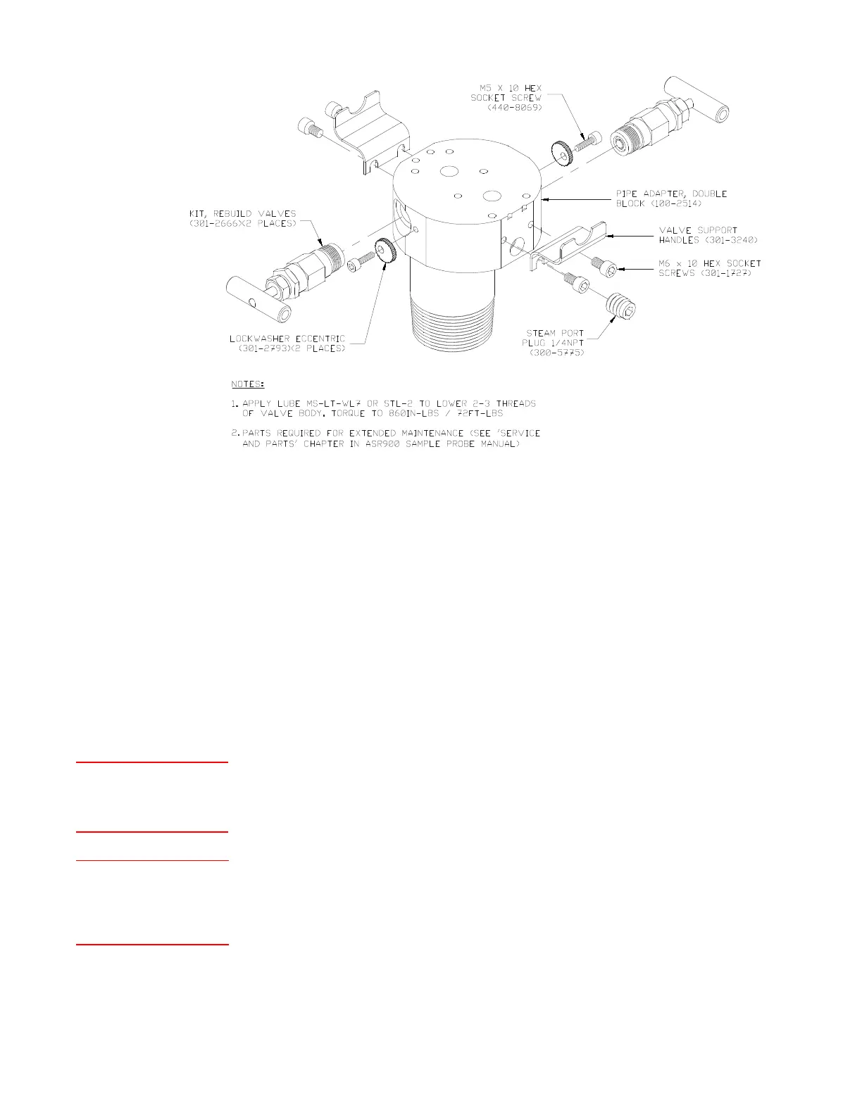
SEE NOTES 1 & 2
Figure 1-4.2.
Optional Double
Block Valve, Special
Applications, 100-2393.
 Loading...