4-14 | Heated Acid Gas Sample Probe (Large Diameter)
12. After the leak-check passes, and maintenance on the Heater Assembly
is complete, replace the Heater Assembly (Figure 4-4):
a. Use a non-abrasive cloth to gently clean the joining surfaces (heat
transfer) of the Heater Block and the Sample Probe.
b. Place the Heater Assembly on the Sample Probe.
c. Apply a high-temperature thread lubricant to the threads of the (4)
M6 x 60 screws (P/N 300-8741, Figure 4-4), replace the screws, and
tighten them to secure the Heater Assembly to the Sample Probe.
The thread lubricant must not contain copper.
13. Replace the Insulating Jacket on the Sample Probe.
14. Power up the analyzer for operation, as described under “Powering
Up the Probe Heater Assembly and Analyzer” in Chapter 3.
The procedure is complete.
!
CAUTION
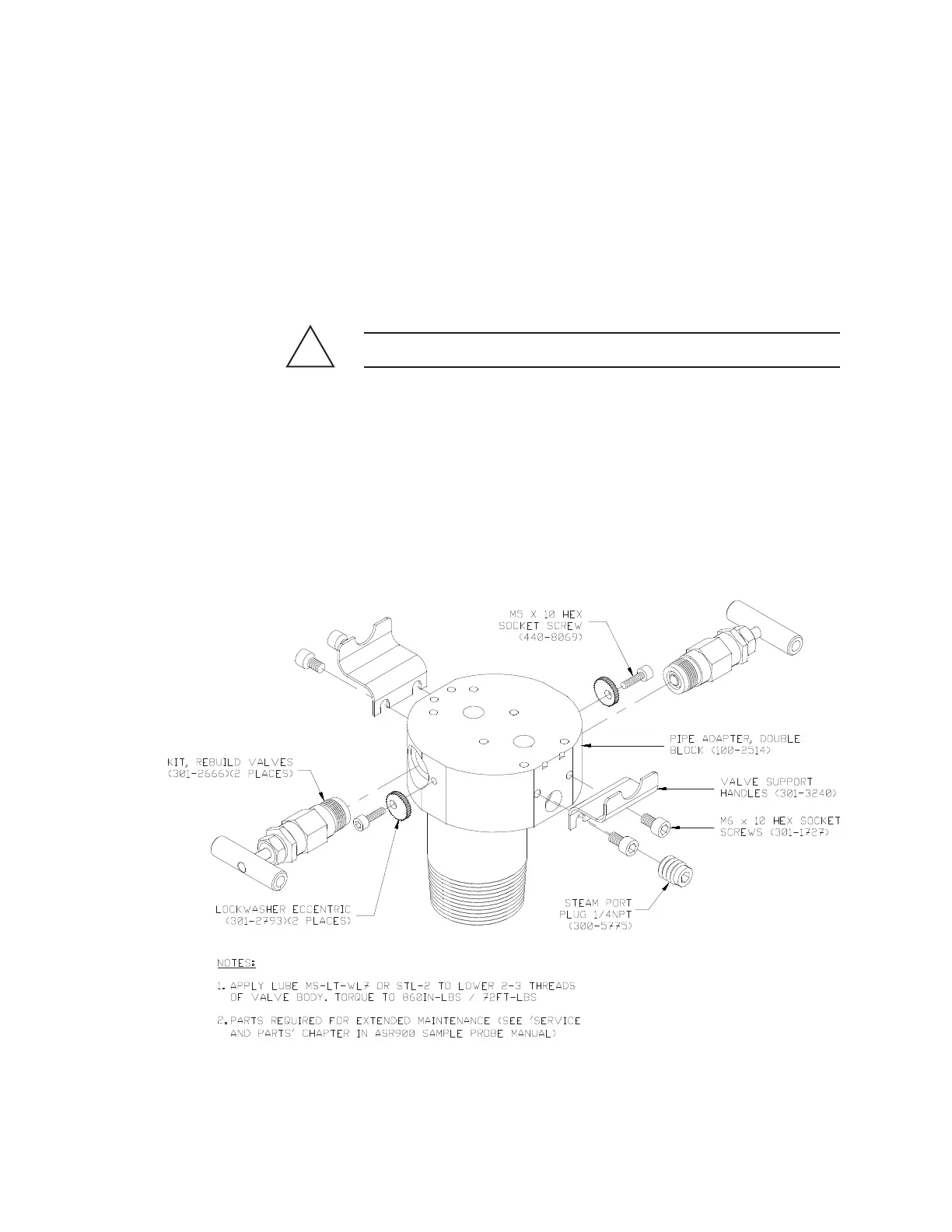
Figure 4-3.
Double-Block Valve,
100-2393.
SEE NOTES 1 & 2
 Loading...