10
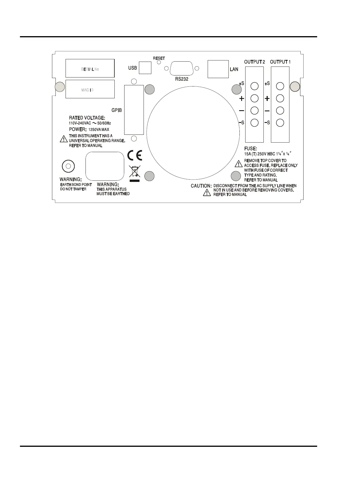
Rear Panel Connections (XPF60-20DP only)
The output and sense terminals for OUTPUT1 and OUTPUT2 are duplicated on the rear panel
terminal blocks and are marked +O/P, −O/P, +S and −S. These connections are paralleled with
their front panel equivalents.
Switch the LOCAL/REMOTE switch to REMOTE when remote sensing is required. When the
rear panel Output terminals are used, the use of remote sense is always recommended to ensure
that output regulation is maintained within specification; connections can be made to either the
front or the rear remote sense terminals but never to both pairs of terminals at the same time.
Switch back to LOCAL when remote sensing is not in use.
RS232 (XPF60-20DP only)
9−pin female D−connector with pin connections as shown below. Can be connected to a
standard PC port using a fully wired 1:1 male-female cable without any cross-over connections.
Pin Name Description
1 RI
Passively asserted (+V through 10k
Ω
Transmitted data from instrument
Received data to instrument
6 RTS
Passively asserted (+V through 10k
Ω
Signal ground is connected to instrument ground.
USB (XPF60-20DP only)
The USB port is connected to instrument ground. It conforms with USB 2.0 (Full Speed) and
accepts a standard USB cable. The Windows plug-and-play functions should automatically

 Loading...
