Rev. 7 105
Appendix
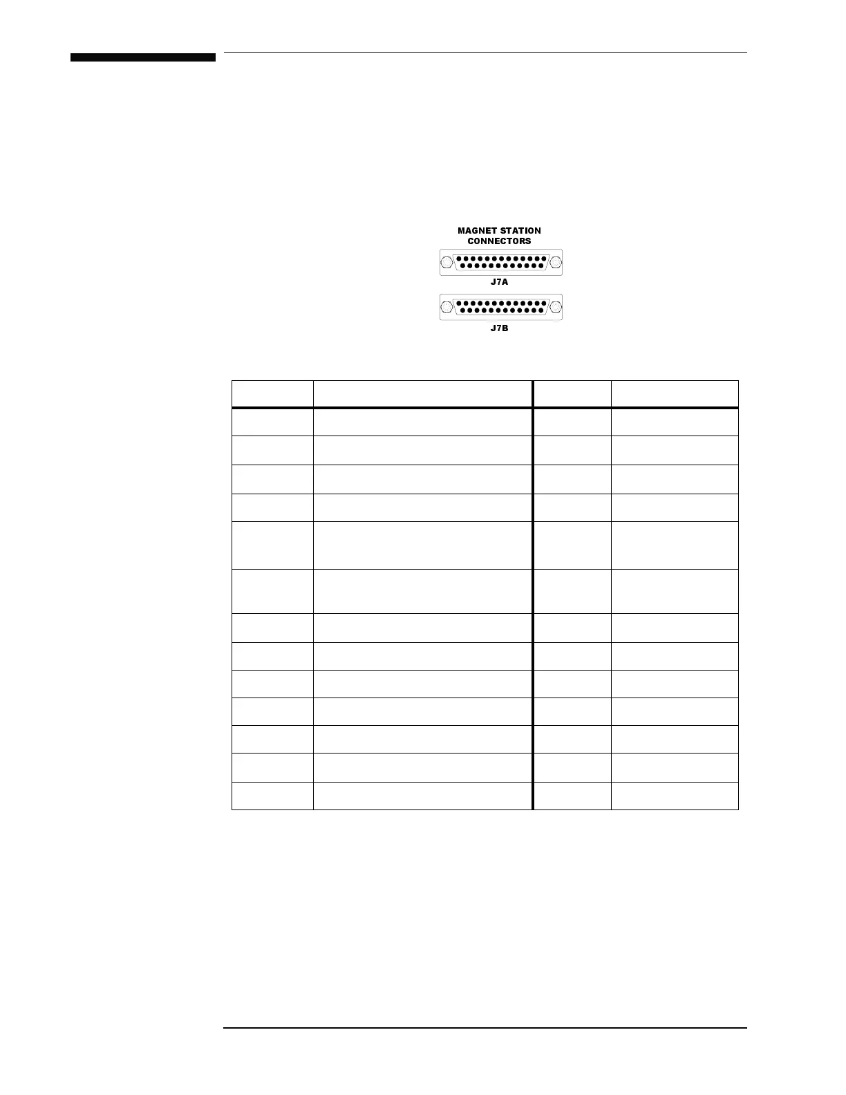
A.1 Magnet Station Connectors
The two 25-pin D-sub female Magnet Station Connectors are identically
wired and connected pin-for-pin internally. Spare wires may be used for
custom coil taps or other signals.
The connectors provide an interface for connecting a single integrated
instrumentation cable from the magnet support stand to the Model 420.
The Model 420 can then be used to distribute the signals to the
Table A-1. Connectors J7A and J7B pin definitions.
Pin Function Pin Function
1 LHe Sensor I+ (Red) 14 Spare
2
LHe Sensor I
− (Black)
15 Spare
3
LHe Sensor V
− (Yellow)
16 Spare
4 LHe Sensor V+ (Blue) 17 Spare
5 Temperature Sensor I+ (Red) 18 External Switch
Heater Current
a
a. See discussion on page 61 for further details on the use of an optional external power
supply for heating the persistent switch.
6
Temperature Sensor I
− (Black)
19 External Switch
Heater Current
7
Temperature Sensor V
− (Yellow)
20 Spare
8 Temperature Sensor V+ (Blue) 21 Spare
9 Persistent Switch Heater (Red) 22 Spare
10 Persistent Switch Heater (Black) 23 Spare
11 Magnet Voltage Tap V+ (Yellow) 24 Spare
12
Magnet Voltage Tap V
− (Blue)
25 Spare
13 Spare
0$*1(767$7,21
&211(&7256
-$
-%