Rev. 7 37
3Operation
This section describes each display and operating mode of the Model 420
instrument and the related functions. Every available menu is illustrated
and described in detail. An example setup of the instrument is presented
in paragraph 3.2.5 on page page 50. An example ramping operation is
presented in paragraph 3.3.6 on page 57.
3.1 Default Display Modes
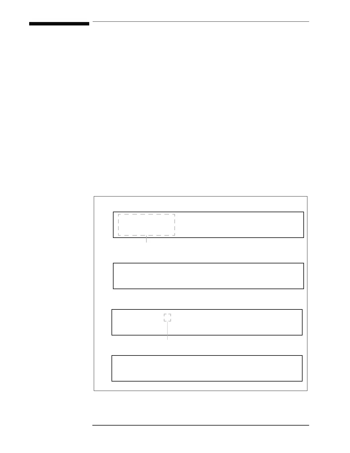
The default display modes are illustrated in the diagram below. There are
four default display modes which can be cycled by repeatedly pressing the
237,21key when not within the setup menu or a setup submenu. The
operating values on the left side of the display are always visible during
any mode of operation or menu selections.
$ × 6WDWXV+ROGLQJ
9V 36ZLWFK+HDWHU21
$ A 6WDWXV5DPSLQJ
9
0 36ZLWFK+HDWHU21
N*× 6WDWXV+ROGLQJ
9V 36ZLWFK+HDWHU21
This portion of the display is always visible.
Default display mode 1: Units of Amps, Supply Voltage Vs.
Default display mode 2: Units of Amps, Magnet Voltage V
M.
Ramping mode character
Figure 3-1. Default display modes.
N*× 6WDWXV+ROGLQJ
9
0 36ZLWFK+HDWHU21
Default display mode 3: Units of kG, Supply Voltage Vs.
Default display mode 4: Units of kG, Magnet Voltage V
M.