Rev. 7 53
Operation
Ramping Functions : Voltage Limit and Ramp Rate
If manual mode operation is desired, press either the or keys for
manual control ramping up or ramping down, respectively.
A voltage limit and ramp rate may be specified from quickly accessible
menus from the front panel keypad. The settings for the voltage limit and
the ramp rate are applicable to both the manual and programmed modes
of operation.
3.3.1.1 Voltage Limit
The voltage limit is accessed by pressing the 92/7$*(/,0,7key
and may be set less than or equal to the maximum output voltage of
the power supply (see Table 3-2 on page 41). The voltage limit does
not require a sign since it functions as both the negative and
positive limit. The voltage limit constrains the commanded output
voltage of a connected power supply to a value less than or equal to
the limit.
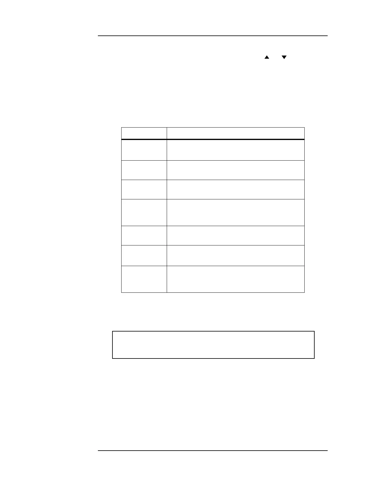
Table 3-5. Ramping states and descriptions.
Mode Description
Ramping Automatic ramping to the programmed current or
field
a
is in progress.
a. The programmed current/field setting is discussed in paragraph 3.3.3.1.
Holding The programmed current has been achieved and
is being maintained.
Paused Ramping is suspended at the current achieved
at the time the PAUSED mode was entered.
Manual Ramping is being controlled by the
0$18$/
&21752/
functions available on the front
panel.
Zeroing
Current
The
=(52 mode is active, and the instrument is
ramping current to 0 A.
At Zero
Current
The
=(52 mode is still active, and the current is
less than 0.1% of
I
max
.
Heating
Switch
The persistent switch heater has been activated.
Ramping is disabled during the persistent switch
heating period.
$ 9ROWDJH/LPLW9
9V p