Rev. 7 3
Introduction
Front Panel Layout
3
5
2
*
5
$
0
0
(
'
&
8
5
5
(
1
7
)
,
(
/
'
9
2
/
7
$
*
(
/
,
0
,
7
5
$
0
3
5
$
7
(
5
$
0
3
3
$
8
6
(
(
6
&
6
(
7
8
3
(
1
7
(
5
2
3
7
,
2
1
0
$
1
8
$
/
&
2
1
7
5
2
/
4
8
(
1
&
+
'
(
7
(
&
7
5
(
6
(
7
=
(
5
2
6
:
,
7
&
+
+
(
$
7
(
5
&
2
1
7
5
2
/
0
$
*
1
(
7
9
2
/
7
$
*
(
2
)
)
0
R
G
H
O
3
R
Z
H
U
6
X
S
S
O
\
3
U
R
J
U
D
P
P
H
U
$
0
,
3
2
:
(
5
$3URJUDPPHG&XUUHQW$
9V B
2
,
1
2
3 4
5 6 8
9 10 11 127
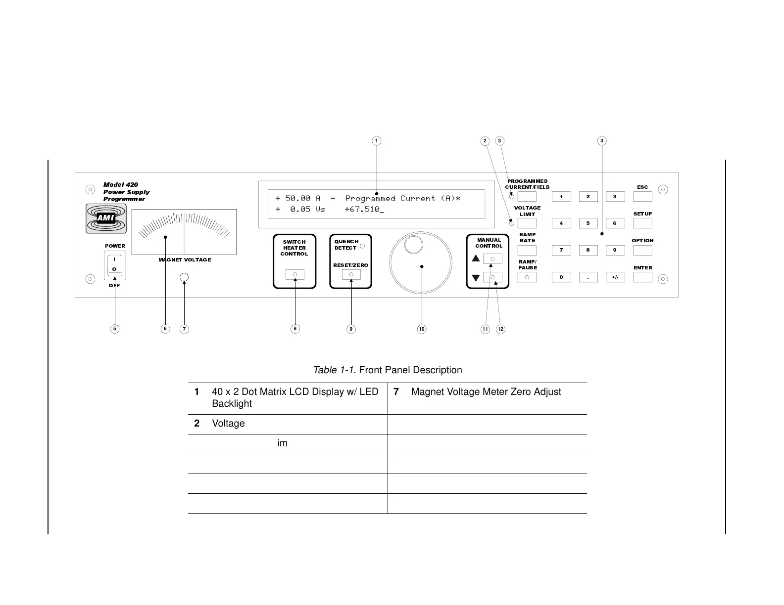
Table 1-1. Front Panel Description
1 40 x 2 Dot Matrix LCD Display w/ LED
Backlight
7 Magnet Voltage Meter Zero Adjust
2 Voltage Limit LED 8 Persistent Switch Heater Control
3 Current/Field Limit LED 9 Quench RESET/ZERO Mode Switch
4 4 Row x 5 Column Keypad 10 Rotary Encoder Dial
5 Power Switch 11 Manual Control UP Key
6 Analog Magnet Voltage Meter 12 Manual Control DOWN Key
1.2 Front Panel Layout