Master-To-Master (M2M)
93
NetLinx Programming Language Reference Guide
The end result of the routing and connection data is that any device or master can communicate with any
other device or Master, regardless of the physical connection of the device. Note that Masters may only
be "connected" to each other via Ethernet/TCP/IP. As an example (FIG. 1 on page 91), NetLinx Studio is
running on a PC connected to System #7 as device number 32002. The routing capabilities of the
NetLinx Master allow NetLinx Studio to download IR codes to the NXC-IRS4 (S=7 D=24), a master
firmware upgrade to NetLinx Master #1, and new touch panel pages to the touch panel on Master #1. All
of this is possible simply by having NetLinx Studio connected to a NetLinx Master with M2M firmware.
Design considerations and constraints
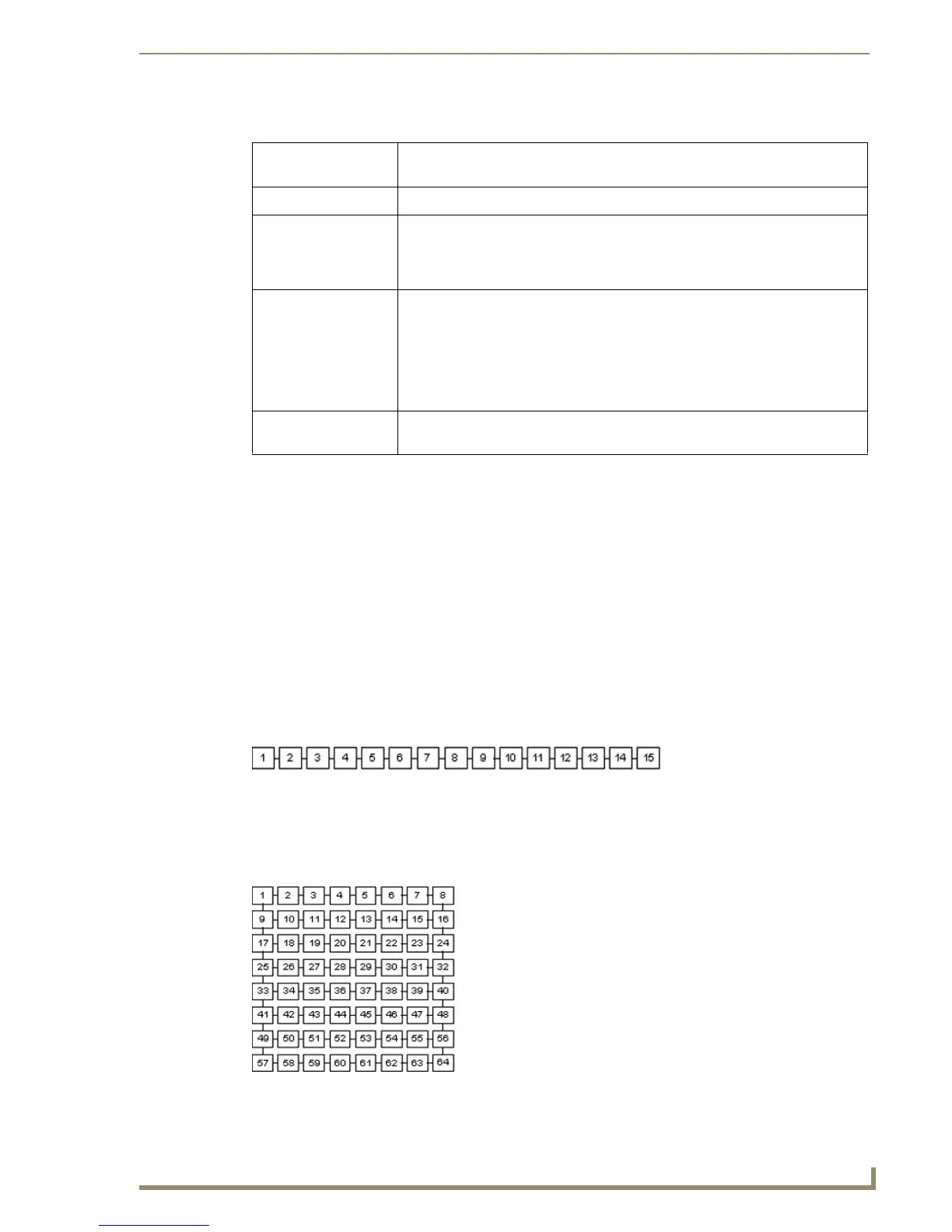
The routing metric limit of 15 usable hops imposes some constraints on the topology of the
interconnected NetLinx masters. While the limit of 15 hops may seem very limiting, this is not really the
case if you carefully architect the topology. FIG. 3 illustrates a single dimensional view of the 15-hop
limit.
This shows a maximum of 15 masters connected to each other, such that any master is routeable to any
other master. FIG. 4 expands FIG. 3 into two dimensions and takes advantage of the fact that each
NetLinx master supports multiple connections to masters.
-> The "->" to the left of system # 5 indicates that system # 5 is the local system
(i.e. the system that the telnet session is connected to).
System column Lists all of the systems in the master's routing table.
Route column Indicates which system number packets are to be routed to in order to get to their
destination. For example, to send a message from System #5 to System #1, the
message must be sent to/through System #2. You can see this by examining the
Route entry for System #1 in the "show route" table.
Metric column Indicates the number of system masters the message must transverse in order to
get to its destination. For the example above, the metric is 2 because the message
must enter System #2, then System #1. Note that a metric of 16 indicates a "dead"
route (i.e. a "dead" route is a route that used to exist but is no longer valid). Fur-
thermore, since the maximum usable metric is 15, there is a limit of 16 masters in
the width plus height of the master topology (see the Design considerations and
constraints section on page 93).
PhyAddress column Indicates the internal connection parameters used by the master to maintain the
connection information.
FIG. 3
Single dimensional view of the maximum number of interconnected NetLinx masters
FIG. 4 Two-dimensional view of the maximum number of interconnected NetLinx masters