ADE9000 Technical Reference Manual UG-1098
Rev. 0 | Page 11 of 86
Digital Integrator
A digital integrator is included to allow easy interfacing to di/dt
current sensors, also known as Rogowski coils. The di/dt sensor
output increases by 20 dB/decade over the frequency range.
To compensate for this increase, the digital integrator applies
−20 dB/decade gain with a phase shift of approximately −90°.
A second-order antialiasing filter is required to avoid noise
aliasing back in the band of interest when the ADC is sampling.
To enable the digital integrator on the IA, IB, and IC channels,
set the INTEN bit in the CONFIG0 register. To enable the
digital integrator on the neutral current, IN channel, set the
ININTEN bit in the CONFIG0 register.
Figure 11 and Figure 12 show the magnitude and phase
response of the ADE9000 digital integrator with the default
DICOEFF = 0xFFFFE000.
100
50
0
–50
–100
–150
0
–40
–30
–20
–10
–90
–80
–70
–60
–50
FREQUENCY (Hz)
FREQUENCY (Hz)
MAGNITUDE (dB)
PHASE (Degrees)
10
–2
0 500 1000 1500 2000 2500 3000 3500 4000
10
–1
10
0
10
1
10
2
10
3
15523-011
Figure 11. Digital Integrator Magnitude and Phase Response with
DICOEFF = 0xFFFFE000
4
–4
–2
0
2
–6
FREQUENCY (Hz)
FREQUENCY (Hz)
MAGNITUDE (dB)
PHASE (Degrees)
35
40 45 50 55 60 65 70 75 80 85 90
35
–89.94
–89.88
–89.86
–89.90
–89.92
–89.94
40 45 50 55 6560 70
75 80 85 90
15523-012
Figure 12. Digital Integrator Magnitude and Phase Response from
40 Hz to 80 Hz with DICOEFF = 0xFFFFE000
If the integrator is enabled, set DICOEFF = 0xFFFFE000.
Phase Compensation
The ADE9000 phase compensation uses a digital filter to
achieve a phase adjustment of ±0.001°. This high resolution
improves the total active energy and reactive energy
performance at low power factors.
The phase calibration range is −15° to +2.25° at 50 Hz.
To achieve this calibration range, the voltage channel is delayed
by one 8 ksps sample, 2.25° at 50 Hz:
°×=° 360
DSP
LINE
f
f
DelayChannelVoltage
°=
°×=° 25.2360
8000
50
DelayChannelVoltage
The current channel is then delayed by a digital filter, according
to the value programmed into the xPHCALx register. The
resulting phase correction depends on the value in the
xPHCALx register. The following equation provides the phase
correction between the input current and voltage after the
combined voltage and current delays. In this formula,
PhaseCorrection° is positive to correct a current that lags the
voltage, and PhaseCorrection° is negative to correct a situation
where the current leads the voltage, such as occurs with a
current transformer:
+×+
××
−
−
+×
−
=°
−
−
−
ω
xPHCALx
ω
xPHCALx
ω
xPHCALx
ω
Correction
Phase
cos2
1
sin2
arctan
cos2
sin
arctan
27
27
27
where ω = 2 × π × f
LINE
/f
DSP
.
The xPHCALx register value can be calculated from the desired
phase correction according to this equation:
27
2
)2sin(
sin)sin(
×
ϕ−×
+−ϕ
=
ω
ωω
xPHCALx
For example, if f
LINE
= 50 Hz, f
DSP
= 8 kHz, and the current leads
the voltage by 0.1 degrees, Phase Correction° = −0.1°. Write
xPHCALx = 0xFFD3_7760 to correct for this.
ω = 2 × π × 50/8000 = 0.03927
7767_3xFFD02918553
2
))1.0(03927.02sin(
03927.0sin)03927.0)1.0(sin(
27
=−=
×
−−×
+−−
=
RADIANS
RADIANS
xPHCALx
DELAY V BY
ONE SAMPLE
2.25° AT 50Hz
INPUT
VOLTAGE
OUTPUT
VOLTAGE
DELAY I
BY UP TO
17.25°
INPUT
CURRENT
CURRENT
TRANSFORMER
SENSOR:
CURRENT LEADS
VOLTAGE
OUTPUT
CURRENT
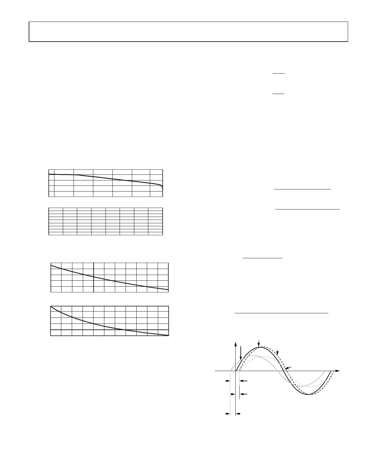
I LEADS V BY UP TO 15°
PHASE COMPENSATION = –15°
ADE9000
15523-013
Figure 13. Phase Compensation Example for Current Transformer,
where the Current Leads the Voltage

 Loading...