ADE9000 Technical Reference Manual UG-1098
Rev. 0 | Page 83 of 86
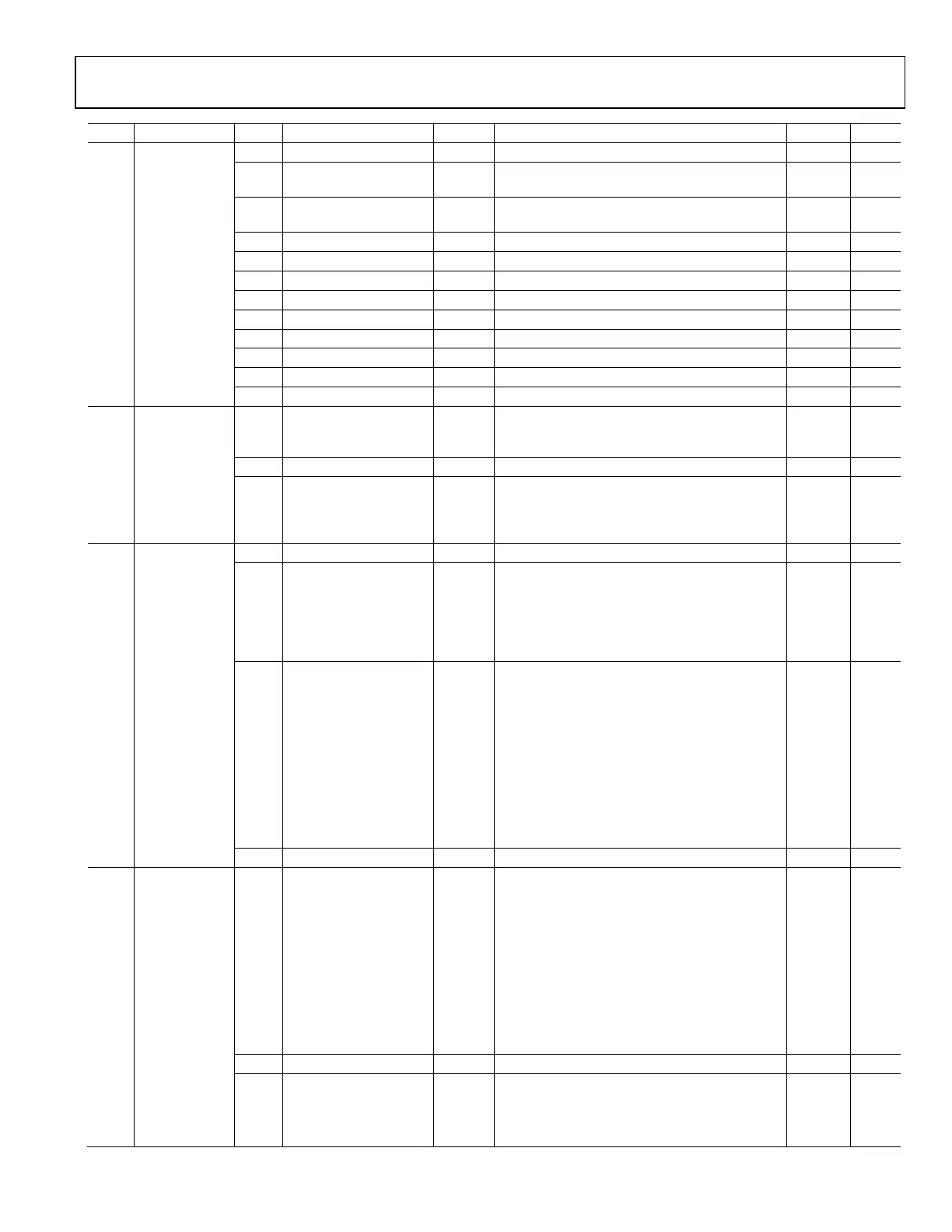
Addr. Name Bits Bit Name Settings Description Reset Access
0x4A2 WFB_TRG_CFG [15:11] RESERVED Reserved. 0x0 R
10 TRIG_FORCE Set this bit to trigger an event to stop the
waveform buffer filling.
0x0 R/W
9 ZXCOMB Zero-crossing on combined signal from VA, VB,
and VC.
0x0 R/W
8 ZXVC Phase C voltage zero-crossing. 0x0 R/W
Phase B voltage zero-crossing.
6 ZXVA Phase A voltage zero-crossing. 0x0 R/W
5 ZXIC Phase C current zero-crossing. 0x0 R/W
4 ZXIB Phase B current zero-crossing. 0x0 R/W
3 ZXIA Phase A current zero-crossing. 0x0 R/W
Over current event in any phase.
1 SWELL Swell event in any phase. 0x0 R/W
0x4A3 WFB_TRG_STAT [15:12] WFB_LAST_PAGE These bits indicate which page of the waveform
buffer was filled last, when filling with fixed rate
data samples.
0x0 R/W
11 RESERVED Reserved. 0x0 R
[10:0] WFB_TRIG_ADDR These bits hold the address of the last sample
put into the waveform buffer after a trigger
event occurred, which is within a sample or two
of when the actual trigger event occurred.
0x0 R
0x4AF CONFIG2 [15:13] RESERVED Reserved. 0x0 R
12 UPERIOD_SEL Set this bit to use a user configured line period,
in USER_PERIOD, for the VRMS½, 10 cycle rms/
12 cycle rms and resampling calculation. If this
bit is clear, the phase voltage line period selected
by the LP_SEL[1:0] bits in the ZX_LP_SEL register
is used.
0x0 R/W
[11:9] HPF_CRN High-pass filter corner (f
3dB
) enabled when the
HPFDIS bit in the CONFIG0 register is equal to zero.
0x6 R/W
000 77.39 Hz.
001 39.275 Hz.
010 19.79 Hz.
011 9.935 Hz.
100 4.98 Hz.
101 2.495 Hz.
110 1.25 Hz.
111 0.625 Hz.
[8:0] RESERVED Reserved. 0x0 R
0x4B0 EP_CFG [15:13] NOLOAD_TMR This register configures how many 8 kSPS
samples to evaluate the no load condition over.
0x0 R/W
000 64 samples.
001 128 samples.
010 256 samples.
011 512 samples.
100 1024 samples.
101 2048 samples.
110 4096 samples.
111 Disable no load threshold.
[12:8] RESERVED Reserved. 0x0 R
7 PWR_SIGN_SEL[1] Selects whether the REVRPx bit follows the sign
of the total or fundamental reactive power.
0x0 R/W
0 Total reactive power.
1 Fundamental reactive power.

 Loading...