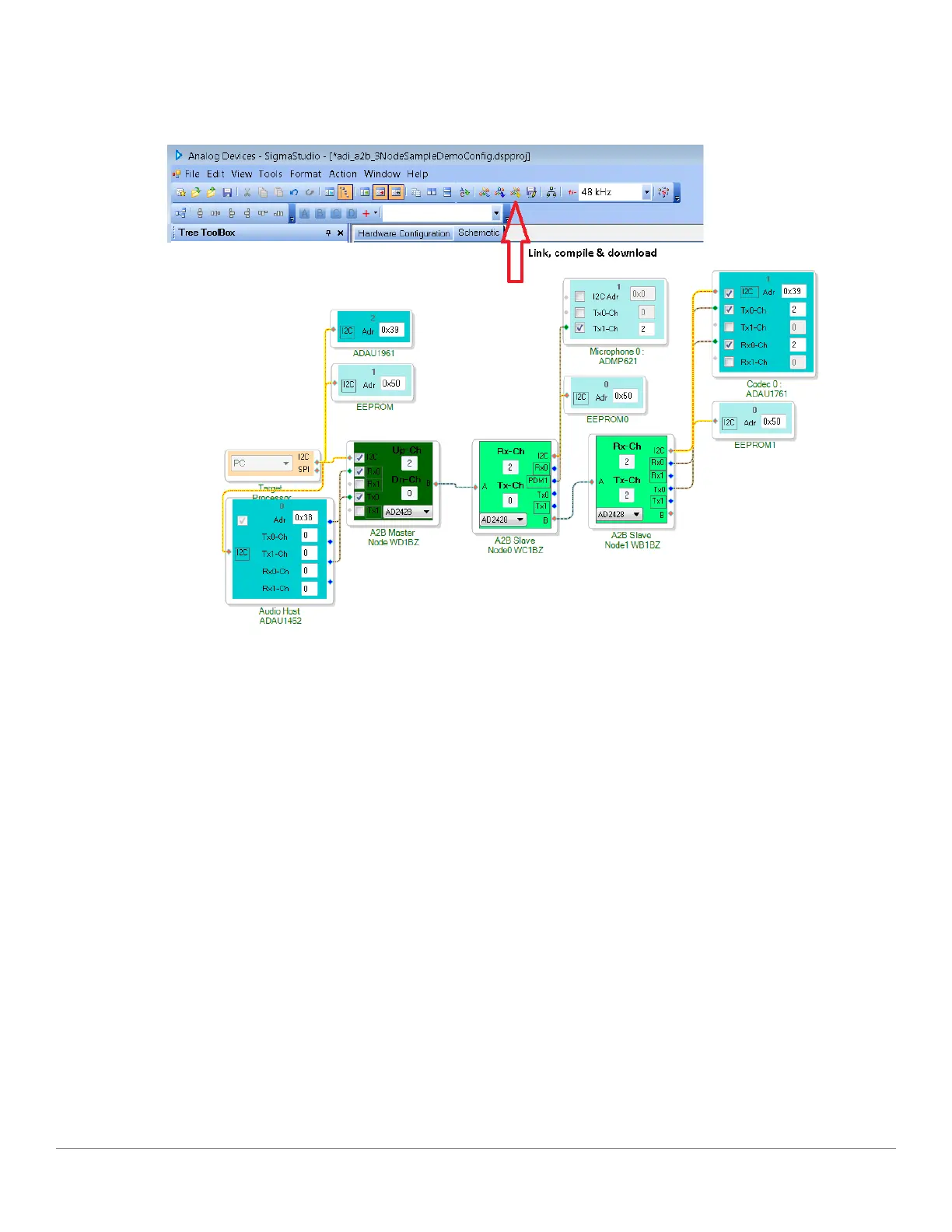
Figure 2-2: Software Schematic for adi_a2b_3NodeSampleDemoConfig.dspproj A
2
B Example Project
4. Before running the demo, follow the Setting up Hardware for an A
2
B System for a three node A
2
B system
guidance. The sample demo configuration appears as shown in the Software Schematic for adi_a2b_3Node-
SampleDemoConfig.dspproj A
2
B Example Project figure. The audio source connected to the slave1 EVAL-
AD2428WB1BZ board plays out of the headphones connected to the master EVAL-AD2428WD1BZ board.
The microphone audio from the slave0 EVAL-AD2428WC1BZ board plays out of the slave1 EVAL-
AD2428WB1BZ board.
5. Use the configuration settings shown in the EVAL-AD2428WB1BZ Evaluation Board Example Slot Assign-
ments figure to properly interface the codec with the A
2
B transceiver. The EVAL-AD2428WB1BZ Evaluation
Board Example Slot Assignments figure shows an example of a downstream data configuration where two slots
are consumed from the A
2
B bus and sent to the local DAC while two additional slots are contributed by the
transceiver taking data from the local ADC.
Using the Software
EVAL-AD2428WD1BZ A
2
B Evaluation Board Manual
2–9

 Loading...


