User Guide EVAL-ADE9113
EVALUATION BOARD SOFTWARE
analog.com Rev. 0 | 16 of 18
Interrupts Panel
The Interrupts Panel allows you to visualize and modify the STA-
TUSx and MASKx registers of all four ADE9113 devices simultane-
ously.
The panel is divided into four main sections representing the four
phases. Each section has three subsections, representing the three
pairs of STATUSx and MASKx registers, and buttons to write to
these registers. Every row in a subsection shows the bit name
and the corresponding values in the STATUSx (circle) and MASKx
(square) registers.
The circles and squares serve as both controls and indicators,
showing the values read after each Read All, and the values in
the circle and square booleans before each Write are the values
written to the registers.
Take the following steps to read from or write to the registers:
1. To read,
a. Click the Read All button to update all registers once.
b. Enable the Reread button to update all registers every 200
ms. Note that to prevent reads and writes from colliding,
the Read All and Write buttons in Interrupts Panel are
disabled when Waveform Scope is in Reread mode, and
vice versa.
2. To write,
a. Disable Reread, if enabled.
b. Select the values you want to write by clicking on the circles
and squares.
c. Click the corresponding Write button to execute the oper-
ation. The program automatically reads and displays the
values in all registers right after each write.
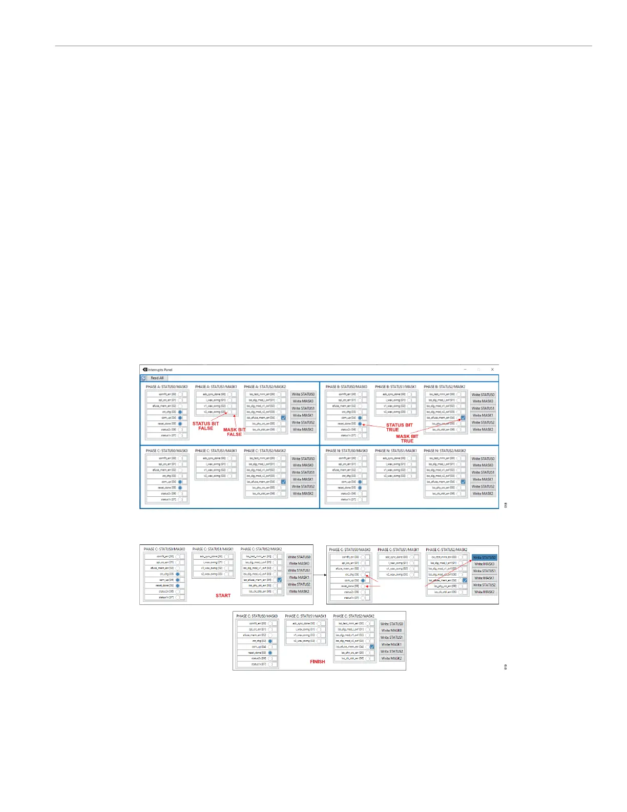
Figure 19 shows how to clear crc_chg on Phase C without clearing
the other interrupts. Because writing true to an interrupt bit clears it,
write a true to crc_chg and false to the other bits in STATUS0 (that
is, 0b00010000). To do this, deselect the STATUS0 bits other than
crc_chg (com_up and reset_done in this case), and then click
the Write STATUS0 button. Because each write is automatically
followed by a Read All, the updated values are visible on the panel
immediately.
Figure 18. Interrupts Panel
Figure 19. Example: Clearing an Interrupt