EVAL-ADAU1467Z UG-1134
Rev. A (Draft) | Page 21 of 55
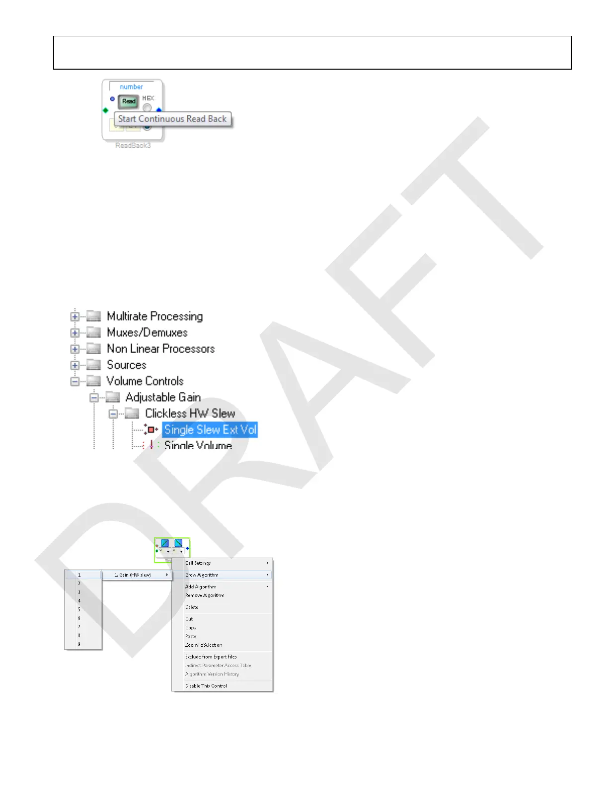
Figure 53. Activating Continuous Readback
iii. For one of the DSP readback blocks, change the
numeric format used to decode and display of the
value of the signal to 32.0 by typing 32 in the left
format box then pressing the Tab key. SigmaDSP
uses a numeric format of 8.24 for audio signals.
7. Add a Single Slew Ext Volume block to the project space
as follows:
a. From the Volume Controls > Adjustable Gain >
Clickless HW Slew folder, click Single Slew Ext Vol
(see Figure 54), and drag it into the project space to
the right of the toolbox.
Figure 54. Single Slew Ext Vol Block Selection
b. By default, the Single Slew Ext Vol block has one audio
signal input. To add another channel, right click in the
empty white space of the Single Slew Ext Vol block, and
select 1 > 1. Gain (HW slew) > Grow Algorithm from
the dropdown menu that appears (see Figure 55).
Figure 55. Growing the Single Slew Ext Vol Block to Two Channels
8. Wire the blocks together as shown in Figure 56. Note that
the position of blocks in the diagram does not matter.
9. Click the Link/Compile/Download button (see Figure 24)
or press F7 to compile the signal flow and download it to the
hardware. The audio signal passes from the S/PDIF receiver
through the ASRCs into the DSP and the EQ filter, and
then out on the S/PDIF transmitter. To change the settings
of the EQ filter, click the blue icon at top of the block. Drag
the control slider in SigmaStudio to change the filter gain
in real-time while the project is running.
The schematic (see Figure 56) shows audio from input Channel 0
and Channel 1 connected to the input of a volume control block.
The volume is controlled by the value of the AUXADC1 channel,
which is controlled by the left potentiometer (R1).
The output of the auxiliary ADC on the ADAU1467 is a 10-bit
integer value in a 32-bit register. The first DSP Readback block,
before the left shift, displays the output of the ADC in 32.0 format,
which can be interpreted as 32 integer bits and 0 fractional bits.
When the potentiometer is turned fully counter clockwise, this
block reads back the minimum ADC output value of 0. When
the potentiometer is turned fully clockwise, this block reads back
the maximum ADC output value of 1023 (within the range of
the component tolerance).
The native audio format of the ADAU1467 is 8.24. In this example,
the volume control multiplies the input signal by a fractional
value ranging from 0 (silence) to 1 (unity gain). Therefore, the
control signal from the ADC must be left shifted 14 bits to scale
the maximum value appropriately.
The second DSP Readback block, after the left shift, displays the
output of the ADC in 8.24 format, which may be interpreted as
8 integer bits and 24 fractional bits. When the potentiometer is
turned fully counter clockwise, this block reads back the minimum
ADC output value of 0. When the potentiometer is turned fully
clockwise, this block reads back the maximum ADC output value
of 1 (within the range of the component tolerance).

 Loading...

