UG-1134 EVAL-ADAU1467Z
Rev. A (Draft) | Page 22 of 55
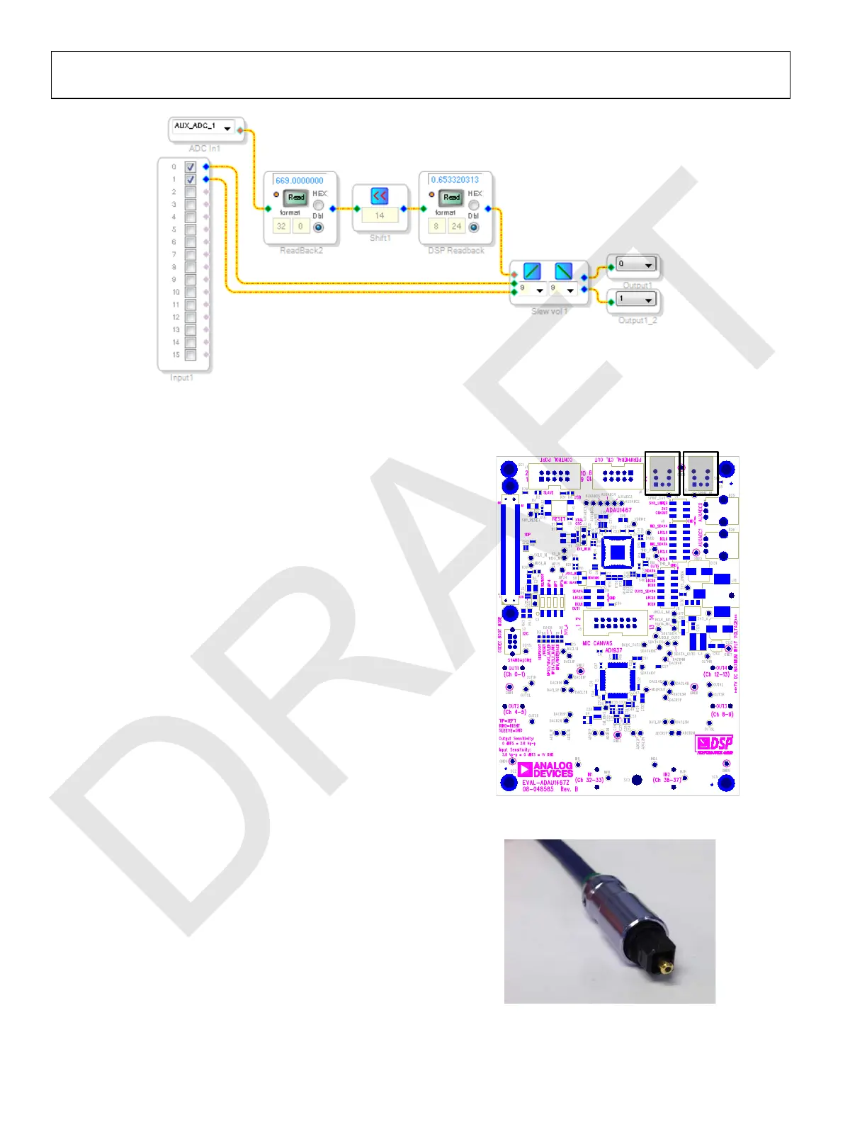
Figure 56. Completed Signal Flow with DSP Readback
S/PDIF INPUT AND OUTPUT
The EVAL-ADAU1467Z evaluation board has two optical S/PDIF
interfaces. One interface is an input that converts the optical
signal to an electrical signal, which is sent to the ADAU1467
S/PDIF receiver (the SPDIFIN pin). The other interface is an
optical output that takes the electrical output from the ADAU1467
S/PDIF transmitter (the SPDIFOUT pin) and converts it to an
optical signal. Figure 57 shows the locations of the optical input
connector and the optical output connector.
S/PDIF Optical Transmitter and Receiver
The ADAU1467 S/PDIF interfaces are connected directly to
optical transmitter and receiver connectors, which convert the
electrical signals to and from optical signals, respectively. The
connectors accept standard TOSLINK connectors and optical
fiber cables (see Figure 58).
Figure 57. Location of S/PDIF Optical Input (J10) and Output (J7), Rotated 90°
Figure 58. TOSLINK Connector and Optical Fiber Cable for the
S/PDIF Input and Output

 Loading...

