UG-1134 EVAL-ADAU1467Z
Rev. A (Draft) | Page 8 of 55
SETTING UP COMMUNICATIONS IN SigmaStudio
To set up communications in SigmaStudio, take the following steps:
1. Start the SigmaStudio software by double clicking the
shortcut on the desktop or by finding and executing the
executable file in Windows Explorer.
2. To create a new project, select New Project from the File
menu or press CTRL + N. (The default view of the new
project is the Hardware Configuration tab.)
3. In the Hardware Configuration tab, add the appropriate
components to the project space by clicking and dragging
them from the Tree ToolBox on the left of the window to
the empty white space located on the right of the window.
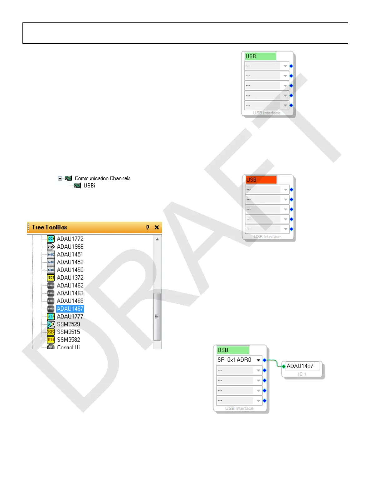
a. Click USBi to add a USBi component from the
Communication Channels subsection of the toolbox
(see Figure 10).
Figure 10. Adding the USBi Communication Channel
b. Add an ADAU1467 component from the Processors
(ICs/DSPs) subsection of the toolbox (see Figure 11).
Figure 11. Adding an ADAU1467
4. Ensure that SigmaStudio can detect the USBi on the USB
port of the PC as follows:
a. When SigmaStudio detects the USBi, the background
of the USB label is green in the USB Interface box
(see Figure 12).
Figure 12. USBi Detected by SigmaStudio
b. When SigmaStudio cannot detect the USBi on the
USB port of the PC, the background of the USB label
is red (see Figure 13). This error can occur when the
USBi is not connected or when the drivers are
installed incorrectly.
Figure 13. USBi Not Detected by SigmaStudio
c. To connect the USBi block (USB interface) to the
target integrated circuit (IC) block of the ADAU1467,
click and drag a line, representing a wire, between the
blue pin of the USBi and the green pin of the IC (see
Figure 14). This connection allows the USBi to
communicate with the ADAU1467. The
corresponding dropdown box of the USBi
automatically fills with the default mode and channel
for that IC. In the case of the ADAU1467, the default
communications mode is SPI, the default slave select
line is 1, and the default address is 0.
Figure 14. Connecting the USBi to an ADAU1467 in the Hardware
Configuration Tab

 Loading...

