EVAL-ADAU1467Z UG-1134
Rev. A (Draft) | Page 9 of 55
CREATING A BASIC SIGNAL FLOW
To create a signal processing flow, take the following steps:
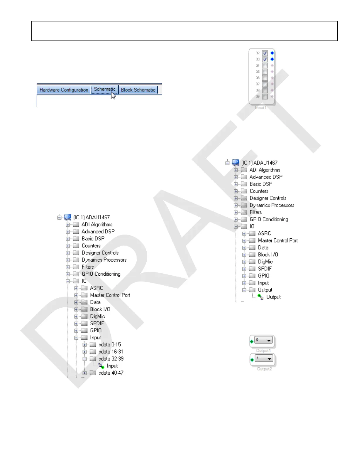
1. Click the Schematic tab near the top of the window (see
Figure 15).
Figure 15. Schematic Tab
2. To add the appropriate elements to the project space, click
and drag the elements from the Tree ToolBox on the left of
the window to the empty white space located on the right of
the window. The toolbox contains all of the algorithms that
can run on SigmaDSP.
a. To add an Input block, from the (IC1) ADAU1467 >
IO > Input > sdata 32-39 folder, click Input (see
Figure 16) and drag it into the project space to the right
of the toolbox (see Figure 17). By default, Channel 0
and Channel 1 are selected. This configuration matches
the analog audio source hardware connections shown
in Figure 7 and Figure 8; therefore, no modifications are
required.
Figure 16. Input Block Selection
Figure 17. Input Block
b. Add two Output blocks as follows, ensuring that these
blocks are assigned to Channel 0 and Channel 1:
i. From the (IC1) ADAU1467 > IO > Output folder,
click Output (see Figure 18) and drag it into the
project space to the right of the toolbox.
Figure 18. Output Block Selection
ii. Repeat the previous step to add another output
(see Figure 19).
Figure 19. Output Blocks
3. To connect each input channel to its corresponding output
channel, click and drag a line, representing a wire, between
the blue pin of the input channel and the green pin of the
output channel (see Figure 20). Input Channel 0 connects
to Output Channel 0, and Input Channel 1 connects to
Output Channel 1.

 Loading...

