Hardware Installation
30 Andover Controls Corporation
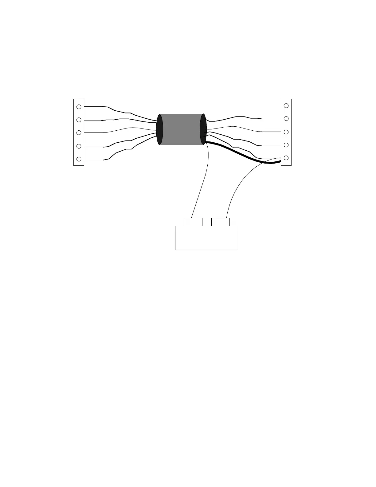
Figure 16 illustrates where you connect the various wires, including
the shield and the 12 V power supply.
Figure 16. Wiring Proximity Wiegand Card Reader to Controller, with 12 VDC
Power Supply
7. Wire the other end of the +12 wire to the positive terminal of a 12
VDC power supply.
8. Attach an extension wire to the GND terminal of the 12 VDC
power supply.
9. Take the other end of the extension wire from the 12V power supply,
the other end of the cable GND wire, and the end of the shield. Slip
all of them under the GND screw on the module; tighten the screw
down on them.
2±
0
1
LED
+12
GND
GND
0/CLK
1/DATA
LED
+5V
extension wire
+12 wire
SHIELD
Card Reader
ACX 780/781
(Two wires and
shield go to GND)
+12 +/-2 VDC
Power Supply
+
GND
from reader
2±
2±
Technical Manuals Online! - http://www.tech-man.com