Hardware Installation
40 Andover Controls Corporation
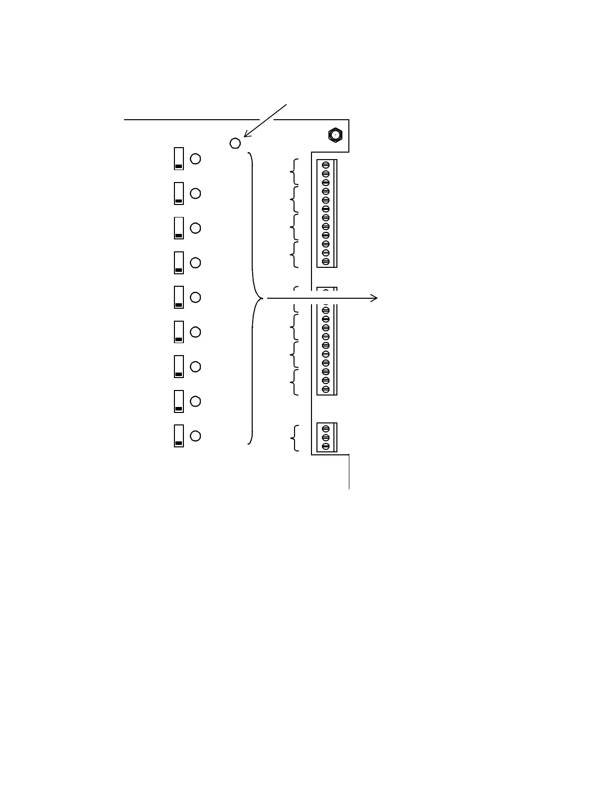
Figure 23. Location of Override and Status Lights
Connecting Main Batteries
The two batteries at the base of the controller cabinet are 12-V 6.5 A-hr
batteries in series. The twisted pair wire to connect them runs from the
power supply to the batteries:
1. Connect the wire to the battery terminal. It is a solderless
connection.
2. Be sure to connect the red wire to the positive terminal, the black to
the negative.
OVERRIDE
OUTPUTS
NC
C
NO
1
NC
C
NO
2
NC
C
NO
3
NC
C
NO
4
ON
OFF
AUTO
OUTPUT 1
ON
OFF
AUTO
OUTPUT 2
ON
OFF
AUTO
OUTPUT 3
ON
OFF
AUTO
OUTPUT 4
ON
OFF
AUTO
OUTPUT 5
ON
OFF
AUTO
OUTPUT 6
ON
OFF
AUTO
OUTPUT 7
ON
OFF
AUTO
OUTPUT 8
ON
OFF
AUTO
OUTPUT 9
NC
C
NO
1
NC
C
NO
6
NC
C
NO
7
NC
C
NO
8
NC
C
NO
9
Status Lights on
if Output Is ON
Override Light
Technical Manuals Online! - http://www.tech-man.com