Hardware Installation
ACX 780/781 Installation Guide 35
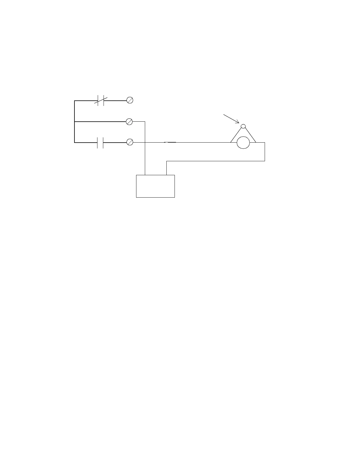
Figure 19 shows the schematic for wiring a DOOR or AUX output if the
circuit is normally open.
Figure 19. Wiring Diagram for DOOR and AUX Form C Outputs if Normally
Open
This configuration shows a normally deenergized lock (when secured)
in a fail secure mode. Always be sure to use “panic” hardware that al-
lows emergency exit from the secured area.
NC
C
NO
C
12/24V
Door Strike
+ –
Power Supply
(UL listed power
supply (APHV) for
UL listed systems)
Oxide Metal
Varistor
(Andover #01-2020-095)
(UL listed burglary-
resistant electric
locking mechanism
(CVXY) for
UL listed systems)
Technical Manuals Online! - http://www.tech-man.com