Hardware Installation
38 Andover Controls Corporation
Figure 21 shows the display. It is located in the upper left corner of the
unit, to the right of the Infinet connection.
Figure 21. Power Supply Status Display
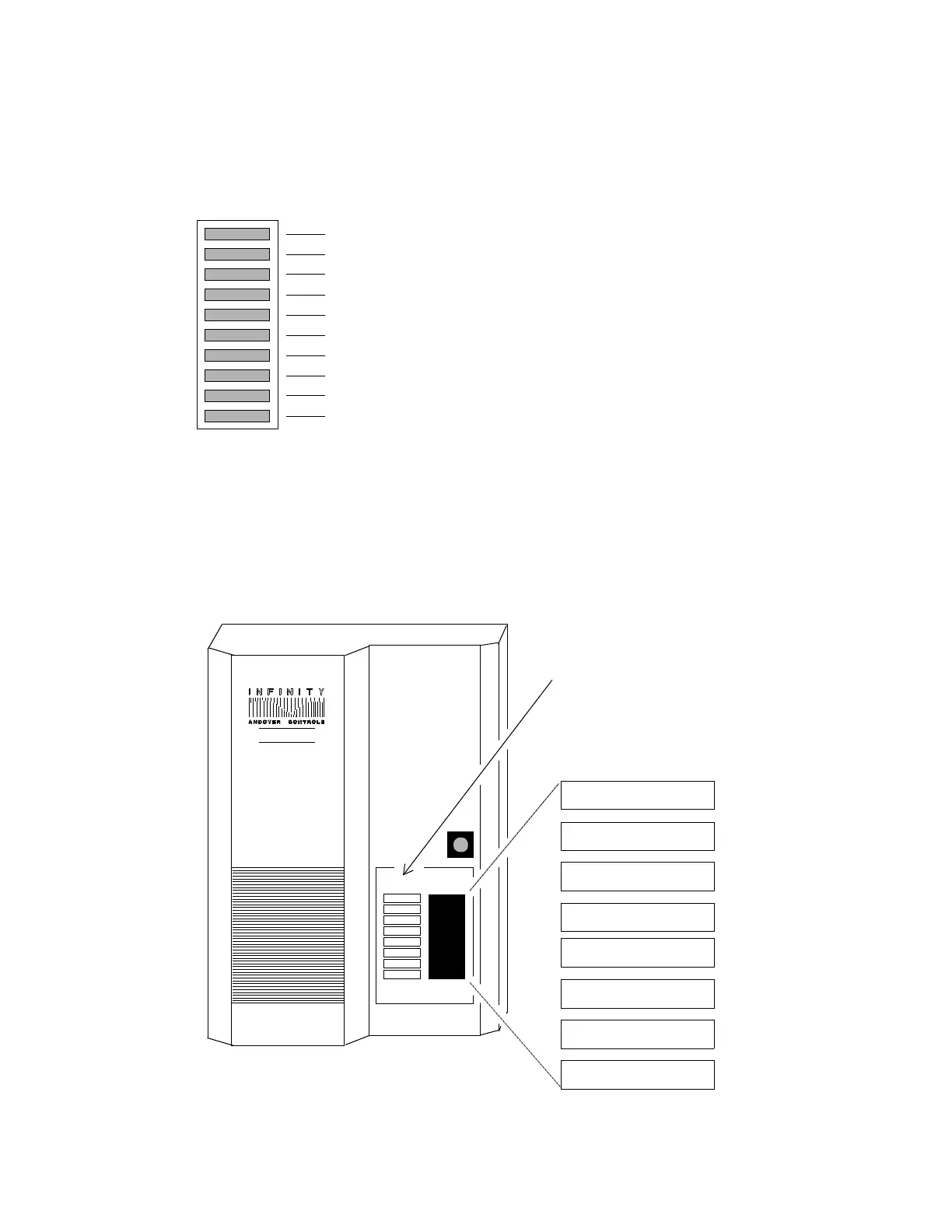
3. The SCAN light on the front of the cabinet begins flashing at a rate
determined by the number of points and programs you have set up.
Figure 22 shows the status lights on the front door of the cabinet.
Figure 22. Status Lights on Front Door of Cabinet Provided
ERROR
NO SRV
CPU
+5V
+24V
+14V
-15V
-5V
AC PWR
SCAN
SCAN
ERROR
NO SRV
AC ON
TD
RD
OUTPUT9
Status Lights on
Cabinet Door That
Correspond to
Doors Wired to
Outputs 1 through 8
Status
ACX780
Technical Manuals Online! - http://www.tech-man.com